
Creating the Flat Slab
(If not continuing from last section, open "EU Example 10_2 Sections.sst" via Help | Tutorials | Open Tutorial Model... from the main menu.)
In the Structure Definition navigation window, click on Add Model | Refined Model in the toolbar at the top of the pane.
Click on
 to create a new 2D Sub Model (GCS, Z=0.0) to the structure.
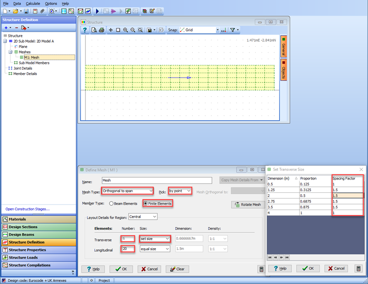
Add a new mesh to this sub-model and create a Finite Element mesh using a Mesh Type of “Orthogonal to span” and pick mode “by point” (remember to set the Member Type: radio button to “Finite Elements”).
Set the Snap mode to “Grid” in the graphics window tool bar and click on the appropriate grid points in the graphic window to define the boundary of the slab (30m x 4m). The display of the coordinates in the top right hand corner can be used for guidance.
Set the number of elements transversely to 6 and longitudinally to 20 then change the “Equal Size” option for the transverse elements to “Set Size”.
In the Set Transverse Size form that should now be visible set the spacing factors as shown below for the elements. Close this form with the ✓ OK button.
Change the Name: of the mesh to “Slab” and close the meshing form in the usual way. A warning message about aspect ratio size may be displayed which will be acceptable so click on Continue.
The next step is to add beam members along the edges of the slab to represent the upstand. This is done by clicking on “Sub Model Members” in the navigation window which opens the Define Sub Model Members form so that additional members can be created.
In the graphics window click on the
 toolbar button to draw a single member . Then click on the bottom left corner node of the mesh and then again on the bottom right node to draw one member.
Repeat this on the top edge of the mesh. These members can then be split into 20 beam element segments by using the Split Beam Element task in the Define Sub Model Members form.
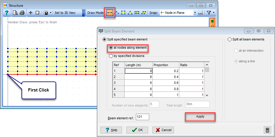
In the split beam elements form select the 'at nodes along element option', click on the edge beam and then click on the Apply button.
Dismiss the information window and repeat for the beam on the top edge of the mesh and then close both forms with ✓ OK.
At this stage it is worth saving the slab model as an intermediate data file so that we can come back to this stage if necessary. Close all the open forms in the normal way and save the model as “My EU Example 10_2 Slab.sst”.