The Unwrap UVW modifier lets you assign mapping (texture) coordinates to objects and sub-object selections, and to edit those coordinates by hand as well as with a variety of tools. You can also use it to unwrap and edit existing UVW coordinates on an object. You can adjust mapping to fit on Mesh, Patch, Polygon, HSDS, and NURBS models using any combination of manual and several different procedural methods.
You can use Unwrap UVW as a self-contained UVW mapping tool and texture-coordinate editor, or in conjunction with the UVW Map modifier. In the latter case, you usually do so in order to use a mapping method unavailable in Unwrap UVW, such as Shrink Wrap. You can animate UVW coordinates by turning on the Auto Key button and transforming the coordinates at different frames.
In using Unwrap UVW, you usually break up the object's texture coordinates into smaller groups known as clusters. That way you can position the clusters precisely over different areas of the underlying texture map for optimal mapping accuracy. Each of these clusters has an outline called a map seam which appears superimposed over the object in the viewports. This helps you visualize the locations of mapping clusters on the object surface. You can toggle this feature and set the line thickness with the Display settings.

Open UVW map seams shown on head model in viewport
Self-Contained Mapper and UVW Coordinate Editor
Rather than creating a large modifier stack by first making a sub-object selection of polygons and then adding a UVW Map modifier to specify the type of mapping, you can use the Unwrap UVW modifier to do both. You can select sub-object vertices, edges, or polygons/patches, store sub-object selections as named selections, map them using planar and other methods, and then edit the UVW coordinates for each sub-object selection, all from within the Unwrap UVW modifier. For example, to map a character's face using three planar maps, you could create three sub-object selections of the front and sides of the face, planar-map the selections individually, and then edit the UVW coordinates for each selection, all without leaving the Unwrap UVW modifier.
Support for Multiple Unwrap Objects
Instancing capabilities in Unwrap UVW make it easy to apply texture coordinates across several objects. First select the objects, then apply Unwrap UVW. When you open the editor, you’ll see the mapping coordinates for all selected objects containing the instanced modifier. The editor shows each object’s wireframe color to help you see which set of coordinates belong to each object.
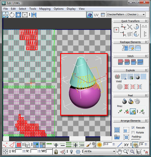
Left: Two objects’ UVW coordinates in the editor, showing wireframe colors
Right (inset): The objects with a shared Unwrap UVW modifier in the viewport
What Happens to Existing UVW Coordinates
When you apply the Unwrap UVW modifier, it stores the object's current mapping coordinates in the modifier. If the object has no mapping coordinates, the modifier creates new ones by applying planar mapping. If the incoming data on the stack is a face-level or polygon-level sub-object selection, then only the UVWs for the selected polygons are brought into the modifier.
When the modifier is evaluated, its UVWs are reassigned to the object flowing down the pipeline. So if the UVWs upstream are changed, the changes won't make it past the Unwrap UVW modifier. If the Unwrap modifier is operating on a selection of polygons, then upstream changes to unselected polygons will still be able to flow past the Unwrap modifier.
Native Support for HSDS, Polygon Object, and Patch mapping
Unwrap UVW supports polygons and Bezier quad and tri patch faces in addition to triangles and quads.
Below is a sample of what the various face types look like based on the incoming type. For HSDS and Poly surfaces, the basic interface remains the same, except that the maximum number of sides per polygon increases from 4 to over two billion. HSDS supports only one level of detail: the level at which the mapping was. Patches have handles on nonlinear vertices. These handles work just like regular patch handles.
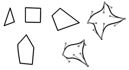
Polygons and faces from HSDS and Poly surfaces; handles appear for nonlinear vertices
Freezing Textures
Although not its primary purpose, you can use the Unwrap UVW modifier to freeze UVWs. You can apply mapping after an animated deformation and have the mapping stick to the object. For example, you can apply Unwrap UVW above a Morpher modifier in the modifier stack, apply planar maps and edit the UVW coordinates. The mapping will follow the morphing geometry.
Procedures
To perform quick planar mapping:
- Apply Unwrap UVW to an object.
- Go to the Polygon sub-object level.
- Make sure
 (Display Quick Planar Map) is on.
 - Select the polygons to map.
The Quick Planar Map gizmo appears as a yellow wireframe rectangle superimposed over the polygon selection, showing the default Averaged Normals mapping. Even though the X button displays by default, Averaged Normals is the default setting.
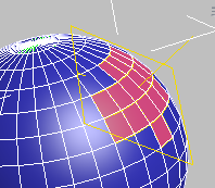
Quick Planar Map gizmo superimposed over selected polygons
- To use a different orientation for the mapping, choose X, Y, or Z from the flyout.
- To apply the mapping, click
 (Quick Planar Map). To map additional polygons, proceed from step 3.
You'll find the Quick Planar Map controls on the Edit UVs rollout of the Unwrap UVW modifier.
To use Unwrap UVW with the standard mapping methods:
- Apply the modifier and a textured material (typically containing an image- or pattern-based Diffuse map) to an object. Set the material to display in the viewports, set at least one viewport to be shaded (for example, press F3 to toggle between wireframe and shaded), and, if necessary, turn off Shade Selected Faces (press F2) for that viewport so the texture mapping is visible.
- Go to the Polygon sub-object level of the Unwrap modifier and make a selection of contiguous polygons. You'll use a single mapping type on this selection.
Within the single modifier, you can apply as many different mappings as you like to different polygon selections.
- Name the polygon selection using the Named Selection Sets function on the main toolbar. This step isn't required, but is recommended so you can easily restore the selection for subsequent mapping adjustments. For example, if you're working on a house, you could use names such as roof and front. Important: After typing the selection set name, be sure to press
 .
. - On the Projection rollout, click the appropriate mapping type button (Planar Map, Box Map, and so on) and then adjust the gizmo using any combination of the transform tools (Move, Rotate, Scale) in the viewports and the Align Options tools (Align To X and so on) on the Projection rollout.
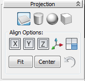
The mapping options on the Projection rollout (top row) from left to right:
Planar, Cylinder, Sphere, and Box
Tip: To reset the mapping to the default, click (Best Align).
 Each time you adjust the mapping gizmo, the texture display in the viewports updates to reflect the mapping changes.
You can also open the editor (Edit UVs rollout
 Open UV Editor) to view the changes in the generated texture coordinates as you adjust the gizmo.
 - To exit mapping for this polygon selection, click the mapping type button again.
- Continue making and naming selections and applying mapping until the entire mesh is mapped. Use the green seam display lines as a guide. If you don't see them, make sure Configure rollout
 Display Group
  Map Seams is on.
 - Open the Edit UVWs dialog (Edit UVs rollout
 Open UV Editor).
 By default, the editor displays a checkered background. To view the map in the material on the object, you need to change a setting.
- At the right end of the editor upper toolbar, click the drop-down list that currently reads CheckerPattern (Checker) and choose the map that's applied to the material.
The map appears as the background.
By default, all the UVW clusters display. To work on one cluster at a time, you need to filter the UVWs.
- On the Edit UVWs dialog
 lower toolbar, click
  (Display Only Selected Polygons).
 At this point, the editor shows only polygons you select in the viewport, and hides the rest. You can select polygons to show directly in the viewport, or choose a named selection set. In the next step, you'll use the latter method.
- On the main toolbar, open the Named Selection Sets drop-down list, and choose one of your named selection sets.
The viewports show the selection as active, and the UVW coordinates for the selection appear in Edit UVWs window.
- In the Edit UVWs window,
 select and move one or more UVW polygons.
 In the viewports, the texture slides around the selected portion of the object mesh.
- Choose a different selection set and edit its UVW coordinates.
Again, the viewport display reflects the editing changes.
- In a viewport, drag a region to select a group of polygons.
The polygons' UVW coordinates display in the Edit UVWs window. This is another way of choosing what you want to work on.
As you can see, from within the Unwrap UVW modifier you can assign multiple mapping types to different, optionally named polygon selections, and then edit the UVW coordinates to fine-tune map placement on the geometry.
This procedure offers a general overview of using the basic Unwrap UVW tools available on the Modify panel and the Edit UVWs dialog. Unwrap UVW provides many additional tools not described in this procedure, particularly in the editor.
For procedures detailing other mapping methods available with Unwrap UVW, see To use Peel Mode, To use Pelt mapping and To use Spline mapping.
To export texture coordinates to a paint program:
- Apply the Unwrap UVW modifier to your object and use the modifier tools to set up the mapping. Texture-coordinate areas that use the same part of the texture map should overlap in the editor.
- From the Edit UVWs dialog menu bar, choose Tools
 Render UVW Template.
 This opens the Render UVs dialog:

- Set the Width and Height values to the output resolution you want in the rendered template. You'll usually get good results by setting the desired width and then clicking Guess Aspect Ratio. Tip: When creating texture maps for gaming and other real-time 3D engines, be sure to set both dimensions to powers of 2: 256, 512, 1024, and so on.
- Change the remaining values as needed. By default, the template is rendered with the edges as white and opaque (alpha=1.0), and background is empty and transparent (background alpha=0.0), but you have a variety of choices here, as detailed in Render UVs Dialog.
- At the bottom of the dialog, click Render UV Template.
This opens a new rendered frame window containing the rendered template as a bitmap. Inspect the output, and if changes are necessary, make them on the Render UVs dialog and re-render.
- When you're satisfied with the results, then on the rendered frame window toolbar, click
 (Save Bitmap), and then use the file dialog to specify the file type and name. Click Save to export the file.
 If you want to use the rendered transparency information in the paint program, be sure to save in a format that supports the alpha channel, such as TIF or Targa.
- Open the exported image in a paint program and use the rendered edges as a guide for painting the texture map. Save the image when done.
Be sure to paint over or erase all the edges so they don't appear in the final texture.
- Back in 3ds Max, create a material, set the Diffuse map to Bitmap, and open the file from the previous step.
- Apply the material to your mesh object.
The painted texture map follows the outlines set up by the exported UVs.
Once you've laid out an object's texture coordinates in the Unwrap UVW modifier editor, you can use this feature to export them to a paint program for creating the texture map.
Example: To use Peel Mode:
- Create or load a model and apply Unwrap UVW to it.
If you want to follow along with this procedure, you can use the same model, which is from the scene file CMan0002-M3-CS.max, included in the [Project Folder]\Scenes folder in your installation of Autodesk 3ds Max 2015. If you're using a computer on which a different user installed 3ds Max, you'll need to look in that user's personal folder.
After opening the file, you might want to select all the bones in the scene and delete them. Also, delete the Skin modifier, apply a new, blank material, apply a UVW Map modifier, and collapse the stack (or use some other method of resetting the UVs).
- Create seams for subdividing the model for peeling. Tip: One handy way to create seams is to select edges (
 ) using the additional tools available at that level, such as
  (Loop). You can then make seams out of the edge selection with
  (Convert Edge Selection To Seams).
 The following illustration shows seams created for the arm:
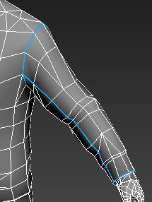
Typically you'd create seams for the entire character mesh before proceeding.
- On the modifier Selection rollout, go to
 (Polygon) sub-object level and select a polygon on the arm.
 - On the Peel rollout, click
 (Expand Polygon Selection to Seams).
 This selects all polygons on the arm enclosed by the seams.

- On the Peel rollout, click
 (Peel Mode).
 The Edit UVWs dialog opens with the arm cluster flattened and ready to work with in Peel Mode, along with other, non-flattened clusters, such as the hand at bottom-left. (Note: Your results might differ, and probably will.)
This demonstrates that, if the Polygon sub-object level is active and any polygons are selected when you activate Peel Mode, only those polygons are peeled. You'll demonstrate this further in the next step.
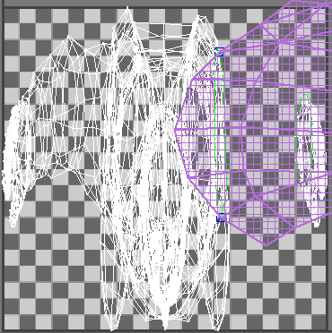
The peeled cluster uses distinctive coloring, which makes it easy to see which part of the texture coordinates you're peeling. The color is violet by default; to adjust the color, change the Peel Color setting.
Note: The editor dialog also provides a Peel rollout with the same Peel tools as on the Modify panel, plus some additional tools for working with pins, which this procedure will cover shortly. - If the clusters overlap, as in the preceding illustration, click
 (Pack: Custom) on the Arrange Elements rollout to separate them.
 - Make sure the Vertex sub-object level (
 ) is active (this happens by default when you turn on Peel Mode) and that no vertices are selected, then drag a vertex in an non-peeled cluster such as the hand. Next, drag a vertex in the peeled cluster.
 To see this, play the following video:
As you can see, dragging a vertex in a non-peeled cluster moves only that vertex, whereas dragging a vertex in a peeled cluster affects the entire cluster. This is one of the main purposes of the Peel feature: moving only a few vertices to reshape a cluster while maintaining its overall topographic integrity.
One of the main purposes of Unwrap UVW is to make the texture coordinates regular with respect to the mesh, so you don't get stretching and other textural anomalies. For better visual feedback when doing so, you can turn on the display of the checker background on the model in shaded viewports.
- Undo any changes from the previous step, then open the drop-down list at the top-right of the dialog and choose CheckerPattern (Checker).
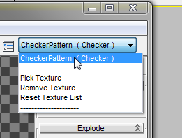
The label already appears, but choosing it from the list activates the pattern, making it visible on the model.
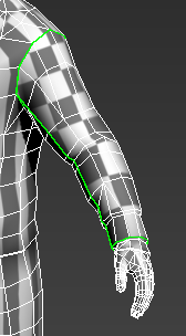
As you can see, the pattern is already pretty regular, thanks to the Quick Peel that Peel Mode applies when you first invoke it. The remainder of this procedure will simply show some of the tools available in Peel Mode.
For example, to make it easier to match the arm or sleeve cluster to an existing texture, you might want to make it more rectangular. But first you'll isolate the cluster.
- Isolate the cluster(s) you want to work on by selecting other clusters and move them out of the way. Make sure the Vertex sub-object level is active and that no vertices are selected.
Sometimes it's a good idea to start the peeling procedure by identifying parts of the cluster whose shape you want to keep, then locking down or "pinning" key texture vertices. The left side of the cluster is already approximately rectangular, so you can start there.
Note: Peel Mode spreads the texture coordinates among pinned vertices (which have blue outlines) on the cluster. Because at least two pins are needed for peeling, the Unwrap UVW modifier chooses two pins by default that are used if you start moving vertices without specifying any pins. However, you can specify which pins to use. You can pin vertices manually with Pin Selected, as shown in the next step. Or when (Auto-Pin Moved Vertices) is on, moving a vertex pins it. In general, it's a good idea to pin any vertices that you want to hold still first, and then move any vertices that you want to reposition.
 - Select the two corner vertices and then click
 (Pin Selected). Then select the default pins and click
  (Unpin Selected).
 To see this, play the following video:
Note the change in size in the cluster after pinning and unpinning the vertices. Because Peel Mode is still in effect, changing the pinned vertices affects the tension of the cluster, resulting in the size change.
Note: You can move a pinned vertex directly by dragging it; it then acts like any other vertex in Peel Mode. The only difference is that it doesn't respond when you drag other vertices. - Change the zoom level if necessary, then move vertices on the irregular side until you get a roughly rectangular shape.
To see this, play the following video:
As you drag, the other non-pinned vertices move as well; Peel Mode does this to maintain the overall topology.
Notice that, the more pinned vertices there are near the vertex you're moving, the greater the amount of local control you have. Also, remember that you can always move a pinned vertex directly.
Tip: It can be useful to align (see Quick Transform rollout) or relax (see Reshape Elements rollout) vertices while in Peel Mode, but they need to be pinned first.Sometimes while you're peeling you might want to subdivide a cluster partially, such as a head texture from the back of the neck to the crown of a head. We'll simulate that in the next couple of steps.
- Starting at the cluster outline, select several edges in a line.
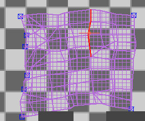
- On the Explode rollout, click
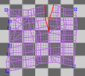
 (Break).
 The edges separate, pulled apart by Peel Mode's retensioning effect.
- Following are some additional tools you might want to use with Peel Mode:
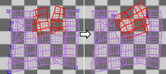
- To create a new cluster, select some contiguous polygons and click
 (Reset Peel). This breaks off the selection as a cluster and applies a Quick Peel.
- To remove pins from vertices, select the vertices and click
 (Unpin Selected). For other pin-related tools, see Pins group.
- To create a new cluster, select some contiguous polygons and click
The Peel toolset provides an implementation of the LSCM (Least Square Conformal Maps) method of unwrapping texture coordinates, for an easy and intuitive workflow in flattening complex surfaces. This procedure shows some of the basic methods available with the Peel tools used on a simple character model. The idea is to give you a rough idea of how to use them in your own projects with more-complex objects such as character meshes.
Interface
After you apply the Unwrap UVW modifier, its interface appears on the Modify panel, comprising the modifier stack plus several rollouts:
Modifier Stack display
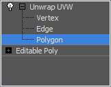
Normally, when you apply Unwrap UVW to an object, the modifier stack provides access to texture coordinates at the Vertex, Edge, and Polygon sub-object levels. The Vertex and Edge sub-object levels are useful for making UVW vertex and edge selections in the viewports, where texture mapping on the object surface is more readily visible, and the Edge level is also useful for setting up edge selections that you can later convert to seams for use with the Pelt and Peel tools.
If you apply Unwrap UVW to an active face or polygon selection of an Editable/Edit Mesh/Poly object, or to an active patch selection of an Editable/Edit Patch object, only that selection is available for editing with the modifier. If you then change the face or polygon selection in the object, the modifier updates the inherited selection and, again, makes only those polygons available for editing.
When you first apply the Unwrap UVW modifier to an object, no sub-object level is active (even though one of the sub-object buttons on the Selection rollout is always highlighted). You can access a sub-object level from the modifier stack or Selection rollout, or you can just open the Edit UVWs dialog, which activates the Vertex sub-object level, unless a different level is already active. While the editor is open, the sub-object level is synchronized among the modifier stack, the Selection rollout (see following) and the Sub-object Selection toolbar on the Edit UVWs dialog. When you activate a sub-object level in one, it's also activated in the others. Similarly, selecting sub-objects in a viewport selects them in the editor and vice-versa.
When you close the editor, the current sub-object level remains active. You can exit this level in the modifier stack display by clicking the modifier name or the highlighted level.
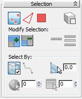
Selection rollout
This rollout contains tools for selecting texture coordinates for manipulating with other tools in the Unwrap UVW modifier.
Some tools here are for selecting sub-objects procedurally rather than explicitly. For example, the  (Grow: XY Selection) tool automatically selects sub-objects connected to the current selection. Such tools work in object (XY) space, as opposed to the comparable tools on the Edit UVWs dialog, which work in texture (UV) space.
For example, say you have a character mesh whose geometry is a single element, but whose texture coordinates are separated into different clusters (head, hands, etc.), for mapping purposes, in the editor. If you go to the Polygon sub-object level of the modifier on the command panel, select a polygon in the viewport, and click the Grow button repeatedly, eventually you'll select the entire model. But if you do the same in the editor, starting with one selected polygon, the most you can ever select with the Grow tool is the cluster to which that sub-object belongs, such as the head.
The following video shows a sphere with Unwrap UVW applied, which was then used to flatten the mapping, resulting in several UVW clusters. First, a few vertices are selected in one cluster in the viewport and the Grow: XY Selection is clicked repeatedly, growing the vertex selection beyond the cluster. Then the vertices are deselected, and a vertex is selected in the cluster in the editor. This time, clicking the Grow button in the editor repeatedly again grows the selection, but not beyond the cluster.
 Vertex/
 Edge/
Edge/ Polygon
- Enables selection at the respective texture sub-object level. These buttons are the equivalents of the sub-object levels on the modifier stack (see preceding) and on the Edit UVWs dialog.
-
 Select by Element XY Toggle
 - When on and and a sub-object level of the modifier is active, clicking an element in the modified object selects all sub-objects at the active level in that element. This is different from the Select by Element UV Toggle on the Edit UVWs dialog toolbar, which applies to clusters of texture coordinates.
Modify Selection group
 Grow: XY Selection
- Expands the selection by selecting all sub-objects connected to selected sub-objects.
For an explanation of the difference between this Grow tool and the one in the UV editor, see the introduction to this section.
 Shrink: XY Selection
- Reduces the selection by deselecting all sub-objects adjacent to non-selected sub-objects.
 Loop: XY Edges
- Expands the selection as far as possible, in alignment with selected edges. Loop applies only to edge selections, and propagates only through junctions of even numbers of edges.
-
 Ring: XY Edges
 - Expands an edge selection by selecting all edges parallel to the selected edges. Ring applies only to edge selections.
Select By group
 Ignore Backfacing
- When on, prevents the selection of sub-objects not visible in the viewport.
 Point-to-Point Edge Selection
- When on, at the Edge level you can select connected edges by clicking successive vertices on the object. While the tool is active, a rubber-band line connects the last vertex you clicked on with the mouse cursor.
To exit from making the current selection, right-click once. At that point, the tool remains active so you can start a new selection elsewhere on the object. To exit the tool completely, right-click a second time.
 Select by Planar Angle
-
When active, you can select contiguous coplanar polygons with one click. Turn this on and use the numeric setting to specify the threshold angle value that determines which polygons are coplanar. Then click a polygon to select it and all contiguous polygons whose angles are less than the threshold value.
Select By Planar Angle is available only at the Polygon sub-object level.
 Select by Material ID: XY
-
Enables polygon selection by material ID. Specify the material ID to select, and then click Select By Material ID.
Select By Material ID is available only at the Polygon sub-object level.
 Select by Smoothing Group: XY
-
Enables polygon selection by smoothing group. Specify the smoothing group to select, and then click Select by Smoothing Group.
Select by Smoothing Group is available only at the Polygon sub-object level.
Edit UVs rollout
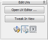
- Open UV Editor
-
Opens the Edit UVWs dialog.
- Tweak In View
- When on, you can adjust one texture vertex at a time by dragging a vertex on the model in the viewport. When you do so, the vertex doesn't move in the viewport, but the mapping changes as a result of the vertex moving in the editor. To see the mapping change as you tweak vertices, the object must be mapped with a texture and the texture must be visible in the viewport.
If the Edit UVWs dialog is open, it updates in real time. Applies at the modifier level and all sub-object levels.
 Quick Planar Map
- Applies planar mapping to the current texture-polygon selection based on the orientation of the Quick Map gizmo.
Using this tool "breaks" the selected texture polygons off as a separate cluster, which is then scaled to fit the editor extents, using the alignment specified on this rollout.
 Display Quick Planar Map
 - When on, a rectangular planar mapping gizmo, applicable to the Quick Planar Map tool only, appears juxtaposed over the polygon selection in the viewports. You cannot adjust this gizmo by hand, but you can use the following control to reorient it.
- X/Y/Z/
 Averaged Normals
 - Choose the alignment for the quick planar map gizmo from the flyout: perpendicular to the object's local X, Y, or Z axis, or based on the polygons' average normals. Note: Although the X icon shows by default, the actual default choice for this setting is Averaged Normals.
Channel rollout
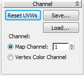
- Reset UVWs
-
Restores the UVW coordinates to their previous state on the modifier stack; that is, the coordinates inherited from the stack by the Unwrap modifier.
Clicking this is almost the same as removing and reapplying the modifier, except that a map assigned in the Edit UVWs dialog is not deleted. For example, if you forgot to turn on the Generate Mapping Coordinates checkbox for an object, and then applied the Unwrap UVW modifier, the modifier would have no UVW coordinates to use and its settings would be wrong. If you then go back in the Stack and turn on Generate Mapping Coordinates, you'd need to click the Reset UVWs button. When you click this button, an alert warns you that you're losing any edits you've made.
- Save
-
Saves the UVW coordinates to a UVW (.uvw) file.
- Load
-
Loads a previously saved UVW file.
Channel group
Each object can have up to 99 different UVW mapping coordinate channels. The default mapping channel (from the Generate Mapping Coordinates toggle in the object’s creation parameters) is always channel 1. You can specify texture coordinates for any channel by using a different Unwrap UVW or UVW Map modifier for each channel.
- Map Channel
-
Sets the identification number of the texture coordinates controlled by this modifier. This channel value corresponds to the Map Channel value set in a map’s parameters, so that the modifier controls how maps set to the same channel are applied to the object surface. Default=1. Range=1 to 99
Please note the following important points about map channels in the Unwrap UVW modifier:
- Each modifier contains edits to only one channel, set in the modifier.
- The mapping in this modifier must use the same channel set in the material's image map (see following list).
- Changing the map channel in the modifier opens a Channel Change Warning dialog that gives you the option to copy the existing edits to the new channel, or abandon them and use the mapping this channel contained before this modifier changed it (see following illustration).
- To apply different mapping coordinates for different maps on the same object, use a new modifier with a unique map channel per image map. You can collapse the stack when finished, and the mapping is preserved.
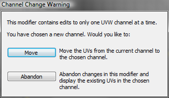
The map channel setting is available in various places in 3ds Max, as follows:
- Generate Mapping Coords This checkbox, present in the creation parameters of most objects, assigns map channel 1 when on.
- UVW Map, UVW Xform, and Unwrap UVWs modifiers These modifiers let you set the map channel to 1 through 99, thus specifying which UVW coordinates the modifier uses. The modifier stack can pass these channels simultaneously for any polygon.
- Material Editor Channel Assignment You assign the channel to be used by a map on the Coordinates rollout at the map level in the Material Editor. The Explicit Map Channel option must be active.
- NURBS Surface Objects and Sub-Objects Let you specify which map channel the surface uses.
- Vertex Color Channel
-
Define the mapping channel as a vertex color channel by choosing this option. Be sure to match any material mapping in the coordinates rollout to be Vertex Color as well, or by using the Assign Vertex Colors utility.
Peel rollout
The Peel tools provide an implementation of the LSCM (Least Square Conformal Maps) method of unwrapping texture coordinates, for an easy and inutuitive workflow in flattening complex surfaces. This rollout also provides access to the Pelt method of unwrapping texture coordinates, as well as seam tools for use by the Peel and Pelt tools.
The Peel tools are available initially only when the Polygon sub-object level is active and texture polygons are selected. The peeling operation you choose applies only to those selected polygons. However, when Peel Mode is active, the Peel Mode button remains active and available no matter which sub-object level you activate. You can select different sub-objects while using Peel Mode, but only the texture coordinates that belong to the polygons that were selected when you first activated Peel Mode are subject to peeling. To peel different polygons, turn off Peel Mode, make a different selection, and then reactivate Peel Mode.
For a brief demonstration of how to use the Peel tools, see this procedure.
 Peel rollout. That rollout also includes a Detach option as well as tools for working with the Pin aspect of the Peel feature. When using Peel, pinned vertices are held in place while the rest of the vertices move.
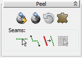
 Quick Peel
- Performs a "best-guess" Peel operation on all vertices (except pinned ones) that belong to the selected texture polygons. To do so, Quick Peel distributes the vertices evenly based on their average locations while trying to maintain existing polygon shapes. If Detach is on, Quick Peel also separates the peeled cluster from the other texture coordinates.
Quick Peel is suitable for simple texture-mapping applications, but for better control, use Peel Mode instead (see following).
Tip: In some cases, repeated applications of Quick Peel can improve the results.  Peel Mode
- Applies a Quick Peel (see preceding) and then stays active so you can adjust the layout of the texture coordinates interactively. You do so by dragging sub-objects in the Edit UVWs dialog window, which redistributes all vertices in the cluster evenly around any pinned vertices. To exit Peel Mode, click this button again.
While Peel Mode is active, peeled polygons use distinctive coloring, which makes it easier to see which part of the texture coordinates you're peeling. The color is violet by default; to adjust the color, change the Peel Color setting.
Activating Peel Mode automatically switches to the Vertex sub-object level, but you can use Peel Mode at any sub-object level. When Detach is on, Peel Mode also separates the peeled cluster from the other texture coordinates.
While Peel Mode is active, you can create seams with the Edit Seams and Point-to-Point Seams tools and they automatically "peel" off as you go. Alternatively, in the editor, select some edges and use the Break tool to split the edges and automatically re-peel the cluster.
When Auto-Pin Moved Vertices is on (the default), moving a sub-object in Peel mode pins (locks) all vertices belonging to the sub-object.
-
 Reset Peel
 - Merges existing map seams of the polygon selection, converts Peel seams to new map seams, and then Peels the resulting clusters. The borders of the selection are separated from the other clusters and become new map seams.
Use Reset Peel to reconnect map seams on previously mapped geometry, or to quickly break off and Peel a selection.
 Pelt
Pelt-
Applies pelt mapping to selected polygons. Clicking this button activates Pelt mode, in which you can adjust the mapping and edit the pelt map.
Note: Pelt mapping always uses a single planar mapping for the entire pelt. If you've applied a different type of mapping, such as Box, and then switch to Pelt, the previous mapping is lost.Tip: For the basic method of using Pelt mapping, see this procedure.
Seams group
Use seams to specify cluster outlines for Peel mapping (see preceding) and pelt mapping, as well as to spline mapping (when you use manual seams). Peel/pelt seams are blue, as opposed to the green Map seams that indicate cluster borders.
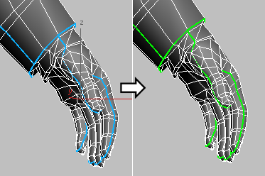
Peel/Pelt seams (left) are converted to Map seams (right) after peeling.
 Edit Seams
-
Lets you create pelt/peel seams by selecting edges with the mouse in the viewports. Available at all sub-object levels of the Unwrap UVW modifier.
Using Edit Seams is similar to standard edge selection, with one difference: Designating seams is cumulative by default. That is, you need not hold
 to add edges to the seam collection. With Edit Seams on:
 - To designate an edge as part of a seam, click the edge. This does not remove edges currently in seams.
- To designate multiple edges as seam edges, drag a region.
- To remove one or more edges from the current seams, hold
 and click an edge or drag a region.
 Point-to-Point Seams
- Lets you specify pelt/peel seams by selecting vertices with the mouse in the viewports. Seams you specify with this tool are always added to the current seam selection. Available at all sub-object levels of the Unwrap UVW modifier.
In this mode, after you click a vertex, a rubber-band line extends from the vertex you clicked to the mouse cursor. Click a different vertex to create a seam, and then continue clicking vertices to create a seam from each vertex to the previous one. To start at a different point in this mode, right-click, and then click a different vertex. To stop drawing seams, right-click again, or click the Point-to-Point Seams button again to turn it off.
Tip: While Point-to-Point Seams is active, you can pan, rotate, and zoom the viewport at any time using contextual controls (middle-button drag, +middle-button drag, turn mouse wheel, respectively) to access a different part of the mesh surface. You can also navigate using the ViewCube and SteeringWheels. After doing so, 3ds Max still remembers the last vertex you clicked and draws an accurate seam at the next click. Similarly, you can adjust the viewport using the viewport control buttons and then return to selecting the seam. If the control requires more than a single click, such as Pan, exiting the control by right-clicking in the viewport restores the rubber-band line, extending from the last vertex you clicked. Tip: The algorithm Point-to-Point Seams uses to calculate a path might create a different seam than what you have in mind. If this happens, undo (
 +Z) and specify the desired path by plotting points closer together.
  Convert Edge Selection To Seams
- Converts the current edge selection in the modifier to pelt/peel seams. These seams are added to any existing seams. Available only at the Edge sub-object level of the Unwrap UVW modifier.
 Expand Polygon Selection to Seams
-
Expands the current polygon selection to the seam outline. If multiple seam outlines exist and each contains selected polygons, the expansion takes place for only one outline (based on the highest polygon ID); the rest are deselected. Available only at the Polygon sub-object level of the Unwrap UVW modifier.
Projection rollout
These controls let you apply and adjust one of four different mapping gizmos to a polygon selection.

 Planar Map
-
Applies planar mapping to selected polygons.
Make a polygon selection, click Planar Map, adjust the plane gizmo using the transform tools and the Align Options tools, and then click Planar Map again to exit.
 Cylindrical Map
-
Applies cylindrical mapping to selected polygons.
Make a polygon selection, click Cylindrical Map, adjust the cylinder gizmo using the transform tools and the Align Options tools, and then click Cylindrical Map again to exit.
Note: When you apply Cylindrical mapping to a selection, 3ds Max maps each face to the side of the cylinder gizmo that most closely matches its orientation. For best results, use Cylindrical mapping with cylinder-shaped objects or object parts.  Spherical Map
-
Applies spherical mapping to currently selected polygons.
Make a polygon selection, click Spherical Map, adjust the sphere gizmo using the transform tools and the Align Options tools, and then click Spherical Map again to exit.
 Box Map
-
Applies box mapping to the currently selected polygons.
Make a polygon selection, click Box Map, adjust the box gizmo using the transform tools and the Align Options tools, and then click Box Map again to exit.
Note: When you apply Box mapping to a selection, 3ds Max maps each polygon to the side of the box gizmo that most closely matches its orientation. For best results, use Box mapping with box-shaped objects or object parts.
Align Options group
Use these controls for aligning the mapping procedurally.
- X/Y/Z
-
Aligns the mapping gizmo to the X, Y, or Z axis of the object's local coordinate system.
 Best Align
-
Adjusts the mapping gizmo's position, orientation, and scale to fit that of the polygon selection, based on the selection's extents and average polygon normals.
 View Align
-
Reorients the mapping gizmo to face the active viewport and adjusts its size and position as necessary to fit the extents of the polygon selection.
- Fit
-
Scales the mapping gizmo to the extents of the polygon selection and centers it on the selection. Does not change the orientation.
- Center
-
Moves the mapping gizmo so that its pivot coincides with the center of the polygon selection.
 Reset Mapping Gizmo
-
Scales the mapping gizmo to fit the polygon selection and aligns it with the object's local space.
Wrap rollout
You can apply regular texture coordinates to irregular objects using these tools.

 Spline Mapping
-
Applies spline mapping to the currently selected polygons. Clicking this button activates Spline mode, in which you can adjust the mapping and edit the spline map.
 Unfold Strip from Loop
- Provides a fast way to unwrap geometry along a linear path, using the object's topology. To use, select an edge loop parallel to the side to unwrap and then click this button. This can cause a significant scale change in the texture coordinates, so typically you would then use a Pack tool to bring them back into the 0 to 1 standard UV range. Tip: Unfold Strip From Loop uses the Ring method to find parallel edges, so for best results use it on regular geometry. You can use the Ring function to see how it will find edges.

1. Original lofted object with default checker pattern applied and edge loop selected
2. After applying Unfold Strip From Loop (closeup view)
3. After selecting parallel edge loops with Ring UV and applying Space Horizontally (closeup view)
Configure rollout
Use these settings to specify modifier defaults, including whether and how seams appear.
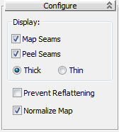
Display group
These settings determine whether and how seams appear in the viewports:
- Map Seams
-
When on, mapping cluster boundaries appear in the viewports as green lines. You can change this color by adjusting the Display seams color.
- Peel Seams
-
When on, peel and pelt boundaries appear in the viewports as blue lines. For more information, see Peel rollout.
- Thick/Thin
-
The display thickness setting applies to both pelt seams and map seams:
- Thick Displays map seams and peel/pelt seams on object surfaces in the viewports with relatively thick lines. The line thickness increases when you zoom the view in and decreases when you zoom out. This is the default choice.
- Thin Seam Display Displays map seams and peel/pelt seams on object surfaces in the viewports with relatively thin lines. The line thickness remains constant as you zoom the view in and out.
- Prevent Reflattening
-
This option is used mainly for texture baking. When on, the version of the Unwrap UVW modifier automatically applied by Render To Texture, named, by default, Automatic Flatten UVs, does not reflatten the polygons. Also, make sure that both Render To Texture and the modifier use the same map channel.
- Normalize Map
-
When on, scales the mapping coordinates to fit into the standard coordinate mapping space: 0 to 1. When off, the mapping coordinates are the same size as the object. The map is always tiled once in the 0–1 coordinate space; the part of the map based on its Offset and Tiling values on
For example, if you take a sphere of 25 units that's planar mapped from the top, and then apply Unwrap UVW and turn off Normalize Map, then when you open the editor, the radius of the sphere's mapping coordinates is 25 units. As a result, the texture map is tiled onto the sphere surface many times. With Normalize Map on, both the sphere and the map fit into the 0–1 coordinate space, so they're the same size.
In general, for best results, leave Normalize Map on. One reason to turn it off would be to turn it off is if you want to map several elements of different proportions with a texture of a specific aspect ratio, such as brick, keeping the texture the same size on each object.