You can use the Milling tab of the Milling Feature Properties dialog to edit the Milling attributes for an Operation.
General attributes
Check allowance — Enter the minimum distance that you want to leave around check surface(s). If left blank, FeatureCAM uses the Finish allowance value.
Cutter comp. — Enable this option to enable Cutter compensation for the operation.
Min. corner radius — Enter a radius to automatically round the inside corners of a feature by the specified radius. The feature shape does not change, but the toolpaths are modified to reflect the rounding.
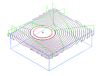
Min. rapid distance % — Enter the minimum distance, as a percentage of the tool diameter, that the tool can use a rapid move for. Moves smaller than this distance use a feed move.
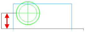
Minimum rapid distance applies to 2.5D milling. Specify the value as a percentage of tool diameter.
This example shows a feature cut with a value of 400%:
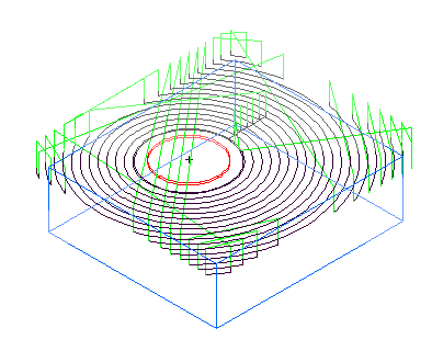
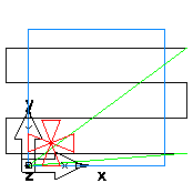
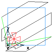
This is the same example with Min rapid distance set to 10% and the tool retracts and rapids between passes.
Stepover rapid distance — This option controls when to retract and plunge on Boss stepovers for NT toolpaths. Enter an absolute distance.
Target horsepower — Enter the ideal [horse] power for the specified width/depth of cut and feed rate on the specified stock material type.
Through depth — Enter a value to add extra depth to the feature. All operations in the feature are updated to have the same value for this attribute. It applies to Slot, Step Bore, Groove, Sides, and Chamfer features.
Total stock — Enter an offset distance around a profile feature to use instead of the stock boundary for the current operation. This applies to rough operations and finish operations where Finish bottom is enabled.
Pre-drill diameter — Enter the diameter for pre-drill holes. Ensure the diameter is large enough to allow the milling tool to enter the stock.
Roughing attributes
These attributes are available to you on the Milling tab when you select a rough pass in the tree view.
Bottom finish allowance — Enter the amount of material to leave on the bottom of a feature after the rough pass. This is only available when Finish bottom is selected on the Strategy tab.
Cleanup passes — Used with a Stepover type of Zigzag, enter the number of cleanup passes to machine.
Curly Corner dialog
Finish allowance — Enter the amount of material to leave on a feature after the Rough pass. You can enter a positive or negative value.
HSM max tool overload % — When the tool approaches overload, a trochoidal path is inserted to avoid the overload. Enter the maximum allowable overload as a percentage of the existing stepover. For example, if you enter an HSM Max tool overload % of 10, trochoidal moves start when an overload condition of 10% is exceeded. This attribute instigates trochoidal machining for NT Spiral and NT Continuous Spiral toolpaths.
HSM profile corner % — Enter the value as a percentage of the tool's diameter. This enables arc fitting of profiles to avoid sharp changes of direction in internal toolpaths. This attribute applies to NT Spiral, NT Continuous Spiral, NT Zigzag and Vortex toolpaths.
HSM smoothing allowance % — Enter the smoothing allowance as a percentage of the existing stepover, to replace the standard offset with a smoother one that can achieve higher feed rates. The percentage defines the maximum deviation from the existing stepover. For example, if you enter an HSM smoothing allowance % of 40, and the existing stepover is 10 mm, the maximum deviation from the original to the smoothed offset is 4 mm.
The advantages are that rounded corners replace sharp corners and curve continuity (not just tangency continuity) is maintained to prevent abrupt changes in force on a machine tool caused by sharp turns in a toolpath. This attribute applies to NT Spiral and NT Continuous Spiral toolpaths.
Mult. rough diameter(s) — Enter a list of roughing tool diameters separated by commas, to enable multiple Rough passes.
Rough pass Z increment — This sets the depth of cut for the rough pass. Enter a step increment for each pass that the roughing routine performs on the part. You can set the depth of cut in several places.
Stock Model Options — Click this button to open the Stock Model Settings dialog. This button is available when you are using a stock model with an NT toolpath for a rough operation.
Toolpath corner % — To round sharp corners, enter a percentage of the tool diameter. Smoothing the sharp corners of the toolpaths gives a more constant tool velocity and reduces the tool load. Enter a toolpath radius larger than the tool radius to minimize the percentage of the tool that contacts the part. This enables enough cooling to take place and avoiding sharp increases in tool load as the tool enters the corners.
Trochoidal cut — Enable this option to use a trochoidal cut on a Simple Groove. Select the direction of the trochoids for a trochoidal cut, from CW (clockwise) or CCW (counter-clockwise).
Trochoidal stepover — Enter the amount to step over between adjacent circles in a Trochoidal cut toolpath.
Vortex min point spacing — Enter the minimum point spacing at which the machine tool can move at the specified feed rate. If the machine tool has too many points to process, it cannot sustain the specified feed rate.
Vortex min radius — Enter the minimum radius of the internal trochoids. Vortex toolpaths use trochoidal moves to maintain a constant feed rate. Higher feed rates require a larger minimum radius. If you do not override this value, a default value is used, which is suitable for a typical machine tool at the feed rate specified for the operation.
Vortex Z lift distance — Enter a Z distance to lift the tool during trochoidal moves to avoid contact between the tool and the surface.
Finishing attributes
These attributes are available to you on the Milling tab when you select a finish operation in the tree view.
Bottom leave allowance — Enter the amount of material to leave on the floor of the feature after the Finish pass. You can enter a positive or negative value.
Bottom semi-finish allowance — This is the amount of material to leave on the floor of a milled feature after the semi-finish operation. It only applies if the Semi-Finish and Finish bottom attributes are selected on a mill feature's Strategy tab. The attribute Finish allowance controls the allowance on the walls of a feature. You can enter a positive or negative value.
Finish allowance — This is a facing parameter for the amount of material to leave after the rough pass. You can enter a positive or negative value.
Finish overlap — This attribute applies to features defined by closed profiles and is the distance that the tool overlaps its starting point on the finish pass. Enter the absolute distance.
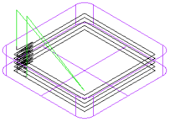
Finish pass Z increment — By default, a milling feature is finished with a single pass along the wall of the feature.
Enter a positive number for Finish pass Z increment to finish the feature with a series of vertical passes. Each pass has a depth of the value entered.
Finish passes — Enter the number of duplicate finish passes to make. If you want to compensate for tool deflection, set Finish passes to more than 1.
HSM max tool overload % — This attribute instigates trochoidal machining for NT Spiral and NT Continuous Spiral toolpaths. When the tool approaches overload, a trochoidal path is inserted to avoid the overload.
HSM profile corner % — This attribute applies to NT Spiral, NT Continuous Spiral, and NT Zigzag toolpaths. Select to allow the arc fitting of profiles to avoid sharp changes of direction in internal corners.
HSM smoothing allowance % — This attribute applies to NT Spiral and NT Continuous Spiral toolpaths. Select this option to replace the standard offset with a smoother one that can achieve higher feed rates.
- Rounded corners replace sharp corners.
- Changes the stepover from a fixed to a variable distance. The percentage defines the maximum deviation from the specified stepover. The maximum percentage is 40% of stepover. So, if you have a 10 mm stepover the maximum deviation from the original to the smoothed offset is 4 mm.
- Maintains curvature continuity (not just tangency continuity) to prevent abrupt changes in force on a machine tool caused by sharp turns in a toolpath.
Minimum ramp distance — This attribute applies to the Finish operation. Enter the minimum horizontal distance for ramping. If the computed horizontal ramp distance is less than this, the tool plunges instead of ramping.
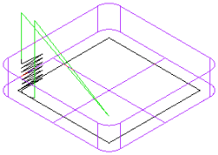
Default ramping for milled finish passes
Ramp diameter — This sets a percentage of the tool diameter to generate a tool motion that approaches the stock along a curve on the finishing pass. The tool arcs only within the distance set in the finish pass allowance, so the ramping effect is small.
Side leave allowance — Enter the amount of material to leave on the walls of the feature after the Finish pass. You can enter a positive or negative value.
Facing attributes
Last pass overcut % — This attribute applies to a Face feature. Enter the distance, as a percentage of the tool radius, that the tool moves past the stock boundary perpendicular to the cut, in the Y direction (unless you have changed the Zigzag angle). The default value is 20% of the tool radius.
Lateral overcut % — Enter the distance, as a percentage of the tool radius, that the tool cuts past the stock boundary in the direction of the cut, on the X axis (unless you have changed the Zigzag angle). The default value is 100% of the tool radius.
Stepover % — Enter the width of cut as a percentage of the tool diameter. The default value is 85%.
Z Increment is the depth of each cut of the facing operation.
Zigzag angle — Enter the angle in degrees (counter-clockwise from X) that you want to use to cut the Face feature.
|
An example of a Face feature with Zigzag angle set to the default 0 deg:
|
The same example with Zigzag angle set to 30 deg:
|
Thread Milling attributes
The following attributes are available on the Milling tab for thread mill features.
Feed to depth override % — Enter the percentage of the Feed setting to use when feeding to depth.
Linear ramp dist. — Enter the length of the linear approach move to a Thread feature.
Ramp diameter % — This attribute controls the diameter of the arc along which the tool ramps on and off the Thread Milling feature. Enter a percentage of the tool diameter.
Ramp angle offset — This angle controls the starting and ending points of the ramp moves of a Thread Milling feature. The tool starts ramping along the arc of radius Ramp diameter % using the Ramp angle offset to determine the start point of the ramping move. If positive, the arc is counter-clockwise.
Start angle — Measured counter-clockwise, the Start angle determines the starting point of the thread.
Start threads — Enter a value greater than 1 for multiple start threads.
Taper approx angle — For tapered threads, the toolpath increases in diameter as well as moving in Z. These moves are approximated with 3D arcs. The Taper approx angle is the angle around the thread that is approximated by a single arc. A 360 must be evenly divisible by the Taper approx angle. For example, if set to 90, a single revolution of the tool is broken into four arcs.
Through — Select Through to increase the hole length by 10% of the hole diameter to account for the drill tip and prevent burring. If Through is deselected, the toolpaths are generated to ensure that the tool does not cut past the end of the thread.
Tooth outside — Enter the number of teeth that are above (if feeding in negative Z) or below (if feeding in positive Z) the thread mill feature for the first pass.
|
|
|
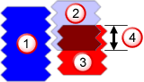
 Thread feature
 Tool revolution 1
 Tool revolution 2
 Tooth overlap
Ramp in feed override % — Enter the percentage of the Feed setting to use when ramping into a feature.
Ramp out Feed override % — Enter the percentage of the Feed setting to use when ramping out of a feature.
Wind fan radius — Enter the radius to use for the wind fan shape. Increasing the Wind fan radius moves the toolpath's start point further from the feature boundary.
Wind fan angle — Enter the angle to use for the wind fan shape. The wind fan angle is a combination of the lead-in and lead-out arc angles.
Chamfer, draft angle, and bottom radius attributes
Manufacturing steps for milled features with bottom radius regions or cross sections.
Draft flat scallop height — For a feature with a taper or bottom radius, enter the maximum allowable height of any scallops left after the Draft flat pass.
Draft radius scallop height — For a feature with a taper or bottom radius, enter the maximum allowable height of any scallops left after the Draft radius pass.
Radius tool scallop height — If you are using a ball-end tool to finish a feature with a bottom radius or tapered wall, enter the maximum allowable height of any scallops left after the Finish pass.
Multi-axis milling attributes
Multi-axis milling and drilling features have these attributes.
Index X coordinate — Optionally enter the absolute X coordinate to use for the index retract move.
Index Y coordinate — Optionally enter the absolute Y coordinate to use for the index retract move.
Index Z coordinate — Optionally enter the absolute Z coordinate to use for the index retract move.
If you do not enter a coordinate, the Z index clearance value is used for the index retract move. Z index clearance is a clearance distance above the stock bounding cylinder. This can result in a Z value for indexing that is outside the valid range for the machine. It can also result in less-efficient retract moves if the part is an irregular shape.
Orientation angle — Enter the initial C-axis position of the part in the machine at the start of the operation.