
Assigning a bitmap or procedural map to the Cutout component makes the material partially transparent. Lighter (higher-value) areas of the map render as opaque; darker areas render as transparent; and values in between are semitransparent.

Click the Material Editor icon on the Main toolbar or press M. Click and hold the icon to show the flyout.
-

 Material Editor > Architectural Material > Special Effects rollout > Cutout map button
-
Material Editor > Raytrace Material > Maps rollout > Transparency button
-
Material Editor > Arch & Design Material > Special Purpose Maps rollout > Cutout map button
-
Material Editor > Autodesk Generic > Cut-outs rollout > Turn on Enable. > Image button
-
Material Editor > Autodesk Metal > Cut-outs rollout > Change Type to Custom. > Image button
-
Material Editor > Other materials that have a Cutout component
Setting the cutout map's Amount to 100 applies all of the map. Transparent areas are fully transparent. Setting the Amount to 0 is the equivalent of turning the map off. Intermediate Amount values are blended with the original Transparency value. Transparent areas of the map become more opaque.
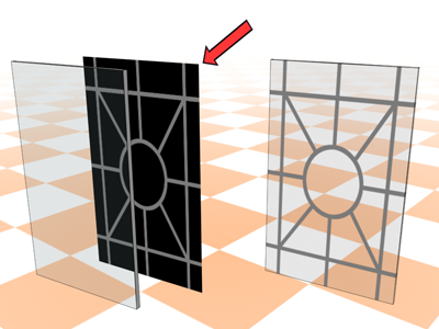
The gray levels of a cutout map determine the amount of transparency.
Procedures
To use a cutout map:
- Click the Cutout map button.
3ds Max opens the Material/Map Browser.
- Choose from the list of
map types, and then click OK.
(If you choose Bitmap as the map type, 3ds Max opens a file dialog that lets you choose the image file.)
- Use the map controls to set up the map.
Alternatively, you can use the
![]() Slate Material Editor to
wire a map node to the Cutout component.
Slate Material Editor to
wire a map node to the Cutout component.