
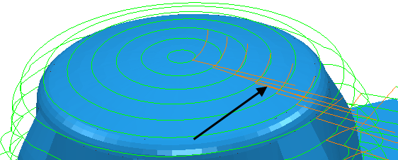
Use the Lead out page to control the movement of the tool after it leaves the stock, at the end of a cutting move.
Type — Select the type of Lead out move to use after each cutting move.
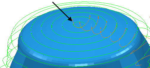
Distance — Enter the length to extend the Lead out move after the cutting move finishes. If this is an arc move, then the distance is the length of the linear tangential move between the arc and the cutting portion of the toolpath.
- With a Distance of 0.
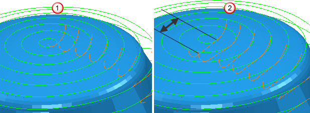
 A Lead out of Surface normal arc with a Distance of 0, an Angle of 90 and a Radius of 5.
 - With a Distance of 10.
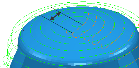
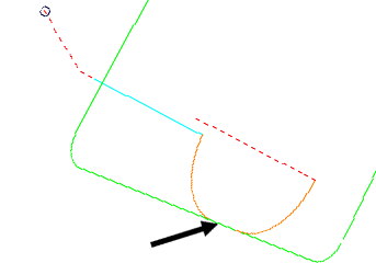
Angle — Enter the angle of the Lead out move relative to the toolpath segment. For arcs, this is the angle spanned by the arc. For lines, it is the orientation relative to the cutting move.
- With an Angle of 90
 . A Lead out of Surface normal arc with a Distance of 0, an Angle of 90 and a Radius of 5.
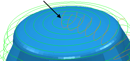
 - With an Angle of 180.
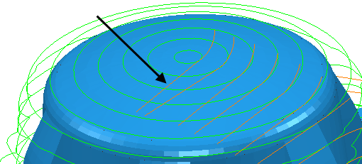
- For a Lead out of Straight and Angle of 0.
- With an Angle of -90.
Radius — Enter the radius of the Lead out arc move.
- With a Radius of 5. A Lead out of Surface normal arc with a Distance of 0, an Angle of 90 and a Radius of 5.
- With a Radius of 10.
Ramp Options — Click to display the Ramp Options dialog, where you can specify how the tool ramps into the stock when using a Ramp-type move. This is available only when Ramp is selected as the Type of Lead out move.
Allow start points to be moved — Select this option to allow PartMaker to move start points on closed loops automatically to try and find a non-gouging position. When deselected, PartMaker will not move the start points.
Overlap distance (tool diameter units) — Enter the distance by which a lead-out move can overlap a closed toolpath segment.
 — Click to copy the Lead in values to the Lead out page.
 — Click to copy the Lead out values to the Lead in page.