
Use Solids Options dialog to specify your preferences for how models are displayed within the Solids window and how you want to work with solid models.
To display this dialog, select the Solids > Solids Options or click  on the Solids Window toolbar.
The following settings are available:
Solid Model Display Quality
Select one of the following options to specify the display quality of the solid model:
- Coarse — PartMaker displays the solid model using relatively large facets. Select this option if you want the model to load more quickly.
- Medium — PartMaker displays the solid model using medium-sized facets. Select this option to balance the time it takes to load the solid model against the appearance of the model.
- Fine — PartMaker displays the solid model using small-sized facets. Select this option to achieve the best appearance of the solid model, but note that this increases the time it takes to load the model, particularly for complex models.
Rendering
- Smoothen Lines — Select this option to reduce the jagged nature of toolpath and profile lines displayed on the solid model.
- Always Visible toolpath — Select this option to make toolpath and profile lines visible even if they are obscured by the solid model. This enables you to see the toolpath and profiles even when they are inside the solid model or behind it.
- Visual Gap Between Solid Model and Toolpath — Select this option to display the toolpath and profiles at a virtual offset to the solid model. This prevents PartMaker obscuring parts of the toolpath or profile if it coincides with the solid model's surface.
Display Control
- Display Profiles and Holes for Active Face window only — When this option is:
- selected, only profiles and holes for the active Face window are displayed in the Solids window.
- not selected, profiles and holes for all Face windows are displayed in the Solids window.
- ViewCube Options — Click to display the ViewCube Options dialog, where you can modify the behaviour and appearance of the ViewCube.
Default Solid Model Color — Click to display the Color dialog, where you can select the default color used to display the solid models.
- Transparency — Enter a value between 0 and 100 to set the default transparency for a model, where 0 displays a solid (opaque) model and 100 displays a fully transparent (invisible) model.
Toolpath Colors for Profiles and Holes — Select the colors PartMaker uses to display different types of profiles and holes on the solid model.
- Moves Parallel to Profile's Plane — In this area of the dialog, you can select colors for toolpath moves that belong in the plane of the profile. These moves apply to Turning and Milling operations:
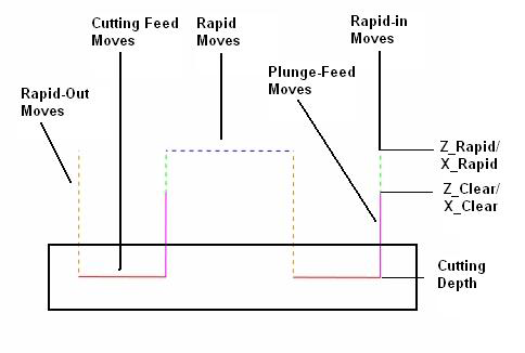
- Cutting Feed Moves — Click to select the color of feed moves used to cut the material.
- Rapid Moves — Click to select the colour of rapid moves that traverse between two sections of the toolpath.
- Holes and Plunge Moves in Milling — In this area of the dialog, you can select colors for toolpath moves that are perpendicular to the plane of the profile. These moves apply to Holes and Milling operations:
- Rapid-In Moves — Click to select the color of rapid moves from the Z_Rapid to the Z_Clear or from the X_Rapid level to the X_Clear level.
- Plunge-Feed Moves — Click to select the color of plunge feed moves from the Z_Clear or X_Clear level to the first cutting depth level.
- Rapid-Out Moves — Click to select the color of rapid moves that go from the final cutting depth level to the Z_Rapid or X_Rapid level.
- Toolpath Points and Tool Axes — In this area of the dialog, you can select colors for toolpath points and tool axes.
- Toolpath Points — Click to select the color to use for the points in a toolpath.
- Tool Axes — Click to select the color to use for tool axes. This option is applicable only to Swarfand Wireframe Swarf finishing toolpaths when using Advanced Surface Machining.
Defaults for Programming on Solids
- Select Edges in Face Plane Only — Select this option if you want to select only the edges that lie in the Face Plane when programming on the solid model.
- Extract Group Parameters from Solid — Use this option to specify the default setting for the Extract Parameters from Solid option on the Profile Group Parameters and Hole Group Parameters dialogs. When the option is selected, PartMaker extracts geometric information from the solid model to complete the fields on the Profile Group Parameters or Hole Group Parameters dialog.
Curve Conversion
- Convert Curved Edges to Arcs — Select this option if you want PartMaker to approximate curved edges into arcs when creating profiles on the solid model.
- Convert Curves to Lines — Select this option if you want PartMaker to approximate curved edges into lines when creating profiles on the solid model.
- Curve Tolerance — Enter the tolerance within which PartMaker approximate curved edges into arcs or lines.
Cylinder Approximation Tolerance — Enter the distance tolerance within which PartMaker approximates a spline surface into a cylinder for the purpose of defining a Face Plane or transferring unwrapped or hole-slot geometry.
Switching to New Face Window — Use these options to specify how the solid model is displayed when moving between Face windows:
- Set View Normal to new Face Plane — Select this option for PartMaker to automatically sets the Solids view to be normal to the Face Plane of the new Face window.
- Set Full Part View — Select this option for PartMaker to automatically reset the Solids view from a sectional view to a full-part view when moving to a new Face window.
Parasolid Export Version — Select the Parasolid version that PartMaker uses when exporting information to Parasolid .x_t or .x_b files. The default option is Current Version, which is the most recent Parasolid version supported by your PartMaker installation. Refer to the What's New guide to find out which version is supported for each PartMaker release.