
This dialog lets you customise the content and layout of the section displayed in the Long Section Window , the Cross Section Window or the Section Window.
The dialog is displayed when Properties is selected from the Section menu or from the context menu displayed by right-clicking the Long Section Window, the Cross Section Window or the Section Window. The options available in this dialog depend on the section being opened.
The dialog contains two tabs:
- Content - allows scaling of y axis, labelling and attributes to be displayed in the relevant section window to be customised
- Layout - allows layout attributes including colours and fonts to be customised
Content tab
The Content tab allows scaling of y-axis, labelling and attributes to be displayed in the relevant section window to be customised.
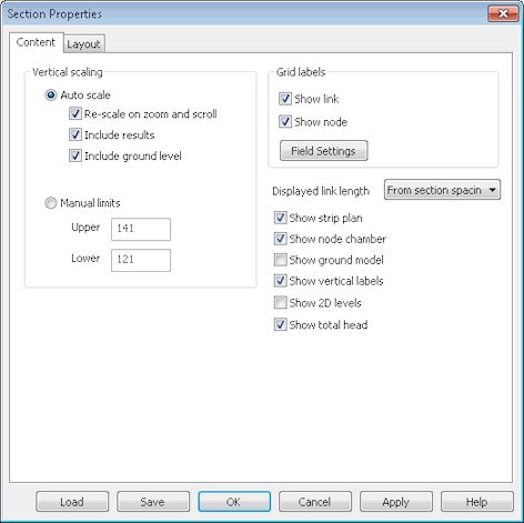
Example dialog for a Long Section
|
Option |
Description |
|---|---|
|
Vertical scaling |
Set manual vertical scale limits for the relevant section window or allow InfoWorks ICM to manage the view scaling itself. Select the Auto Scale option to enable automatic scaling. The options are:
Check the Manual Limits button to set user defined height limits for the data displayed on the view. In the two boxes, enter the height above datum for the top and bottom of the display. |
|
The options below are available for the Long Section Window. |
|
|
Grid labels |
Use the Show Link and Show Node check boxes to show or hide link and node custom labels at the bottom of the window. Click on the Field Settings button to change the data that is shown on the labels. This displays the Network Label Field Settings dialog. |
| Displayed link length |
Only available for InfoWorks networks. Select an option for the method of displaying link lengths in the long section:
|
|
Show strip plan |
Choose whether the simple plan, running along the top of the display, is shown. The strip plan identifies the relative position of nodes along the section. The strip plan is effectively a one-dimensional representation of the GeoPlan Window display. Nodes and links are displayed using the options set up on the GeoPlan Properties dialog. |
|
Show node chamber |
Use this check box to show or hide the below ground part of the manhole. With the box unchecked, the node is shown as a single line, thus simplifying the view. Checking the box allows you to see a visual representation of the water level rising in the manhole. |
|
Show ground model |
Use this check box to show or hide the line representing heights from the currently loaded ground model. |
|
Show vertical labels |
Use this check box to show or hide the vertical labels for nodes and river reach sections. |
|
Show 2D levels |
Only available for InfoWorks networks. Check the Show 2D Levels box to include display of a line representing levels calculated from 2D simulation results. Where a link intersects a 2D Zone mesh element a level will be plotted on the long section. The level value plotted is calculated as the sum of the height at the centroid of the mesh element plus the 2D level result. |
| Show total head |
Only available for InfoWorks networks. Use this check box to show or hide the line representing link total head results Total head is calculated as: H + v2/2g where: H = level above datum (mAD) v = velocity (m/s) g = acceleration due to gravity (m/s2) |
|
The options below are available for the Section Window |
|
| Show ground model |
Use this check box to show or hide the line representing heights from the currently loaded ground model. |
| Show ground fill |
Use this check box to show or hide the fill colour beneath the ground model line. When turned on, ground fill may obscure the flood level and mesh ground level lines. |
| Show flood level |
Use this check box to show or hide the line representing water level heights. |
| Show mesh ground level |
Use this check box to show or hide the line representing the levels of the intersecting 2D zone mesh element heights. |
|
The options below are available for the Cross Section Window (InfoWorks networks only). |
|
| Show ground model | Use this check box to show or hide the line representing heights from the currently loaded ground model. |
| Show inside water level |
Enabled when displaying cross section for a river reach bank. Use this check box to show or hide the line representing water level heights in the river reach. |
| Show inside ground level |
Enabled when displaying cross section for a river reach bank. Use this check box to show or hide the line representing ground level heights in the river reach. |
| Show outside water level |
Enabled when displaying cross section for a river reach bank. Use this check box to show or hide the line representing water level heights for the structure connected to the river reach on the other side of the bank. |
| Show outside ground level |
Enabled when displaying cross section for a river reach bank. Use this check box to show or hide the line representing ground level heights for the structure connected to the river reach on the other side of the bank. |
| Show varying bank level |
Enabled when displaying cross section for a river reach bank with breach. Use this check box to show or hide the line representing the bank level as it changes over time. Note that the varying bank level may not match the fixed bank level trace exactly. This is because levels are adjusted during simulation to ensure that points are not set below the elevation of objects that the bank abuts. See Modelling Breaches in Banks and Linear Structures for details. |
Layout tab
The Layout tab allows attributes including colours and fonts to be edited.
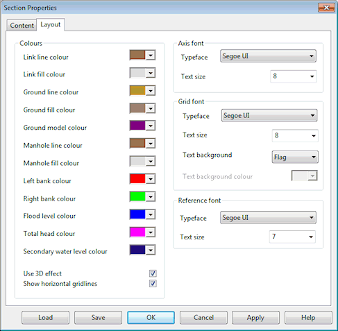
Example dialog for a Long Section
Example of font settings for a Long Section in InfoWorks ICM
|
Option |
Description |
|---|---|
| Colours |
In this section, specify colours for the different components of the section window of interest. Long Section Window:
Section Window:
Cross Section Window options enabled when displaying a cross section for a river reach bank:
|
| Show horizontal gridlines | Tick this check box to display dashed horizontal lines for each tick mark. |
| Use 3D effect | Tick this check box if to apply a visual 3D effect to manholes and links. |
|
Axis font |
This section allows customisation of the axis labels font on the Section Window. The attributes that can be edited are: Typeface and Text Size. |
|
Grid font |
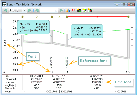
Available for Long Section Window only. This section allows customisation of the grid labels font in the Long Section Window. The grid labels are displayed at the bottom of the window. The attributes that can be edited are: Typeface, Text Size, Text Background, Text Background Colour. The labels display the IDs of the objects contained in the long section by default, (see Content tab to learn how to change the data shown on the labels).
|
|
Reference font |
Available for Long Section Window only. This section allows customisation of the autolabels displayed on the Long Section. The attributes that can be edited are: Typeface and Text Size. The autolabels are usually under the form of vertical text indicating the node IDs. |
Buttons
The following buttons are available on the dialog:
|
Button |
Description |
|---|---|
| Load | Displays the Load Network Editor Properties Dialog which is used to load a previously saved set of section window settings. |
| Save |
Displays the Network Editing Properties - Save Options Dialog which is used to save the current section window settings. |
|
OK |
Closes the dialog and applies changes to the section window. |
|
Cancel |
Closes the dialog and does not apply any changes to the section window. |
|
Apply |
Applies changes to the section window without closing the dialog. |
| Help | Open related help topics. |