
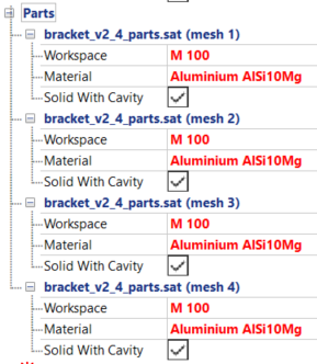
Set up physical conditions for simulation
- In the Properties Panel, click the
, and assign the values for
Workspace and
Material to each of the meshes, as shown below.
- Collapse the Parts tree, then right-click to create a Boundary Condition, BC1. Repeat this action to create BC2.
- Expand BC1 on the tree, and set Boundary Condition Type to Restraint.
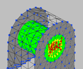
- Position the model so you can see the inner surface of the two vertical bolt holes, then press Ctrl+Left Mouse Button and draw a rectangle inside each of these bolt holes to select a group of points.
- In the Toolbar,
Selection panel, set the
Tolerance value to
25, and click
Flood Fill.
All the points on the inner surface of each bolt hole should be selected.
- Expand BC2 on the tree, and set Boundary Condition Type to Force. Also set the Z value to 2e3.
- Position the model so you can see the inner surface of the horizontal bolt hole, then press Ctrl+Left Mouse Button and draw a rectangle inside the bolt hole to select a group of points.
- In the Toolbar,
Selection panel, click
Flood Fill to apply the force to all points inside the bolt hole.
- Click .