Prepare the solid, skin, and lattice parts
We will work with an Initial Graphics Exchange Specification (IGES) file that was split into four parts in a CAD program.
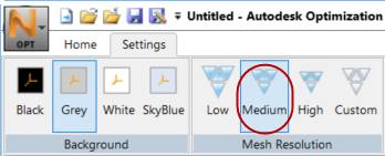
- Along the top of the
Optimization Utility Toolbar, click the
.
- Click
, then navigate to where you stored the
Optimization Utility parts, and import
bracket_v2_4_parts.sat.
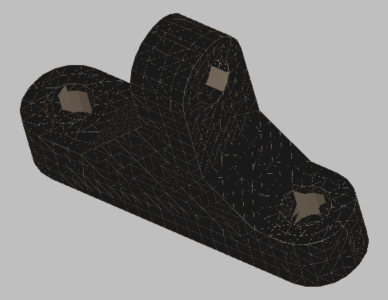
On the Properties Panel, note that the file contains four separate meshes. We will set the properties for each one on its Part tree.
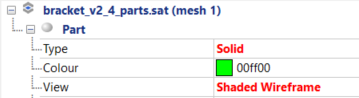
- For meshes 1, 2, and 4, set the following properties (any bright color is fine):
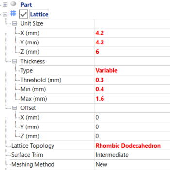
- For mesh 3, set the
Type to
Lattice, and the
View to
Shaded Wireframe, then set up lattice properties as follows:
- Also for mesh 3, right-click
, and repeat this command so you have three regions. Set their properties as follows:
- Region 1 – Type=Solid, Value=0.4 mm
- Region 2 – Type=Skin, Skin Thickness Type=Variable, Threshold, Min & Max values all 0.4 mm
- Region 3 – Type=Hollow
- In the
Properties Panel, click
Solid - Region1 and assign it to the three bolt holes by pressing Ctrl+Left Mouse Button and selecting a few polygons on the inside of each hole.
- In the Toolbar,
Selection panel, set the
Tolerance level to
25 and click
Flood Fill.
The surface region is applied to the entire inner surface of each hole.

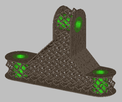
- In a similar process assign
Skin - Region2 to the bottom, top, and flat sides adjacent to the bolt holes, as shown below.
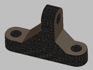
- Assign
Hollow - Region3 to the remaining curved surface.
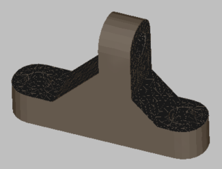
- In the Toolbar,
Actions panel, click
Create Component. The result should appear as shown below.