
Use the Probed Parallel Plane item to construct a plane parallel to a reference plane that passes through one or more probed points.
To create a Probed Parallel Plane:
- Open a Geometric group in the Sequence Tree.
- Click Geometry tab > Planes panel > Probed > Probed Parallel Plane.
The Probed Parallel Plane dialog contains the following areas:
Name — Enter a name for the item. The name is used in the inspection sequence, in the Report and Info tabs, and when referencing the item in other items.
Use nominals — Select this check box to enter or change the item nominals, and to compare the item measurements to their nominal values. Deselect this check box to disable comparisons with the item nominals.
When this check box is selected, an in-tolerance
 or out-of-tolerance
 indicator is displayed on the measured item's icon in the inspection sequence; the border of the item
label is coloured to indicate whether the measurements are within tolerance; and the tolerance, nominal, deviation, and error values of the item are shown in the report.
indicator is displayed on the measured item's icon in the inspection sequence; the border of the item
label is coloured to indicate whether the measurements are within tolerance; and the tolerance, nominal, deviation, and error values of the item are shown in the report.
When this check box is deselected, the Nominal boxes are disabled, no tolerance indicators are displayed and no tolerance, nominal, deviation, and error values are shown in the report for this item.
 and select
From CAD Entity. To replace the nominals with the item's measurements in the current Measure, click the button and select
From Active Measure.
and select
From CAD Entity. To replace the nominals with the item's measurements in the current Measure, click the button and select
From Active Measure.
Visible — Select this check box to display the item in the CAD view.
Output in report — Select this check box to include the item in the report.
Coordinate system — Select the alignment relative to which the item's measurements are to be reported.
To specify the alignment during the inspection, select <Active Alignment>. You can then select the alignment from the Active alignment list, or by adding an Active Alignment item to the inspection sequence.
Material condition — Select Mean, Maximum Material Condition, or Least Material Condition to specify the method you want to use to determine the location of the plane.
You can construct a line or plane parallel to an existing item, through probed points. Select:
- Mean to create a line or plane running through the average height of the probed points. For example:
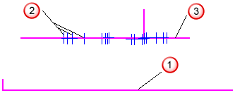
 Reference plane
 Probed points
 New plane
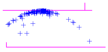
 - Maximum Material Condition to create a line or plane running through the point furthest from the reference item. This positions the item at the highest point of a boss.
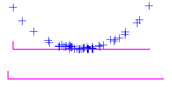
- Least Material Condition to create a line or plane running through the point nearest to the reference item. This positions the item at the lowest point of a hole.
Hide sign information — Select this check box to report the distance measurement as an absolute value. Deselect this check box to report the distance measurement as positive or negative relative to the vector of the reference plane.
Reference plane — Select the plane you want to use to construct the parallel plane.
 to
to
Normal vector — Specify the normal vector of the plane.
Distance — Specify the nominal perpendicular distance from the probed point to the reference plane.
Point sources — Select this tab to use probed points from other items to measure this item.
For example, you can use the tab to create a measured cylinder by combining measurements from probed circles at the top and bottom of the feature.
To specify the sources for the probed points, select one or more items in the
Available sources list, and then click
 to add them to the Selected
sources
list.
to add them to the Selected
sources
list.
To remove sources, select the items in the
Selected sources list, and then click
 .
.
Click OK to close the dialog and save your changes.