
Use the Offset Plane item to construct a plane by applying offsets to selected points. If you select more than three points, PowerInspect calculates a best-fit plane through the points.
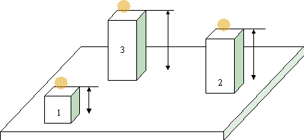
For example, you can use an Offset Plane item to construct a plane from points located on different surfaces of a part. PowerInspect creates a new plane through the offset points. This diagram shows three points with positive offsets:
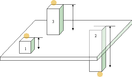
You can also use negative offset values from the offset points. This diagram shows point 2 as a reversed probed point with a negative offset:
To create an Offset Plane item:
- Open a Geometric group in the Sequence Tree.
- Click Geometry tab > Planes panel > Constructed > Offset Plane.
The Offset Plane dialog contains the following areas:
Name — Enter a name for the item. The name is used in the inspection sequence, in the Report and Info tabs, and when referencing the item in other items.
Use nominals — Select this check box to enter or change the item nominals, and to compare the item measurements to their nominal values. Deselect this check box to disable comparisons with the item nominals.
When this check box is selected, an in-tolerance
 or out-of-tolerance
 indicator is displayed on the measured item's icon in the inspection sequence; the border of the item
label is coloured to indicate whether the measurements are within tolerance; and the tolerance, nominal, deviation, and error values of the item are shown in the report.
indicator is displayed on the measured item's icon in the inspection sequence; the border of the item
label is coloured to indicate whether the measurements are within tolerance; and the tolerance, nominal, deviation, and error values of the item are shown in the report.
When this check box is deselected, the Nominal boxes are disabled, no tolerance indicators are displayed and no tolerance, nominal, deviation, and error values are shown in the report for this item.
 and select
From CAD Entity. To replace the nominals with the item's measurements in the current Measure, click the button and select
From Active Measure.
and select
From CAD Entity. To replace the nominals with the item's measurements in the current Measure, click the button and select
From Active Measure.
Visible — Select this check box to display the item in the CAD view.
Output in report — Select this check box to include the item in the report.
Coordinate system — Select the alignment relative to which the item's measurements are to be reported.
To specify the alignment during the inspection, select <Active Alignment>. You can then select the alignment from the Active alignment list, or by adding an Active Alignment item to the inspection sequence.
Offset list — Specify the points used to construct the plane, the offset of each point, and the method by which each point is measured:
- Name — Click the box and enter a name for each point.
- Value — Click the box and enter the offset distance for each point. The offsets are applied in the normal of the plane calculated from the probed points.
Offsets for both types of probed point are calculated from the theoretical contact point. The way in which you calculate the offset value depends on the way in which the point is measured.
For probed points, Offset Value
 = Apparent Offset - Probe Radius. For example:
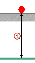
For reversed probe points, Offset Value
 = Apparent Offset + Probe Radius. For example:
- Type — Choose an option from the list to specify how the point is created. Select:
- Probed point to use the probed point.
- Reversed probed point to use the inverse of the probed point. This enables you to simulate taking the point from the opposite side of the probed surface.
- Reference points to use a point from another sequence item.
To add more points to the list, click  . To delete the last point in the list, click
  . You cannot delete the original points.
Select the alternative solution — If you specify only three points, two different planes can be constructed. Select this check box to use the alternative solution to that selected by PowerInspect. Selecting this check box has no effect when you specify more than three points.
Normal vector — Specify the normal vector of the plane.
Flatness — Enter the Maximum acceptable difference between the points with greatest positive deviation and greatest negative deviation. If the difference between the greatest positive deviation and the greatest negative deviation exceeds the Maximum value, the flatness is out-of-tolerance.
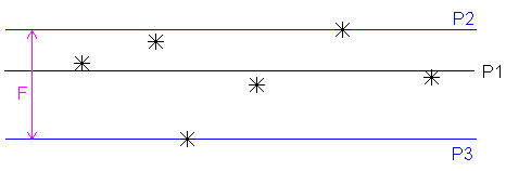
When you use more than three points, PowerInspect creates a best-fit plane (P1) that minimizes the deviations of the points. It then runs two parallel planes (P2 and P3) through the furthest positive and negative points, and the distance between P2 and P3 (F) is reported as the Flatness of the plane. If this distance is greater than the Maximum value, the flatness is out-of-tolerance.
Click OK to close the dialog and save your changes.
If you selected Probed Points or Reversed Probed Points as the offset type, you must probe the points to create the offset plane. If you selected only Reference Points as the offset type, PowerInspect creates the plane from the specified points.