
Use the Slice profile page to create a toolpath by slicing the model at a specific Z height and then creates a profile pass at that Z height.
Slices — Select how to define the slice.
- Boundary — Generates the slice from the current boundary. The Z height is either at the Z coordinate of a 2D boundary or at the maximum Z coordinate of a 3D boundary.
- Pattern — Generates the slice from the current pattern. The Z height is either at the Z coordinate of a 2D pattern or at the maximum Z coordinate of a 3D pattern.
- File — Imports the slices from a DUCT picture file. Enter the file path or click
 and select the file.
- Toolpath — Extracts the slice data from the active toolpath.
- Flat — Generates the slices on the flat areas. The flat areas are determined by the options selected on the Flat machining page.
Slice Editor — Select to display the Slice Editor toolbar. Use the Slice Editor to delete and save toolpath slices.
Cut direction — Select the milling technology.
Select a Cut Direction from the following:
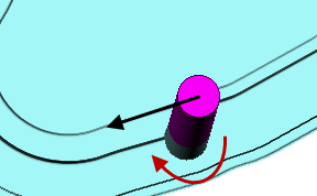
- Climb — Select to create toolpaths using only climb milling, where possible. The tool is on the left of the machined edge when viewed in the direction of tool travel.
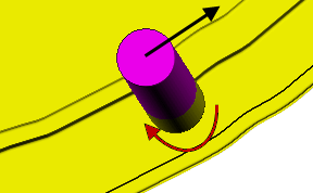
- Conventional — Select to create toolpaths using only conventional or upcut milling, where possible. The tool is on the right of the machined edge when viewed in the direction of tool travel.
- Any — Select to create toolpaths using both conventional and climb milling. This minimises the tool lifts and tool travel.
When you have several profile passes you can have a different cut direction for the final profile pass.
- Profile — Select the cut direction of the final profiling pass.
- Additional profiles — Select the cut direction of all passes except the final profiling pass.
Tolerance — Enter a value to determine how accurately the toolpath follows the contours of the model.
Thickness — Enter the amount of material to be left on the part. Click the
Thickness
 button to separate the
Thickness
box in to
Radial thickness
button to separate the
Thickness
box in to
Radial thickness
 Axial thickness
 . Use these to specify separate
Radial and
Axial thickness as independent values. Separate
Radial and
Axial thickness values are useful for orthogonal parts. You can use independent thickness on sloping walled parts, although it is more difficult to predict the results.
. Use these to specify separate
Radial and
Axial thickness as independent values. Separate
Radial and
Axial thickness values are useful for orthogonal parts. You can use independent thickness on sloping walled parts, although it is more difficult to predict the results.
Radial thickness — Enter the radial offset to the tool. When 2.5-axis or 3-axis machining, a positive value leaves material on vertical walls.
Axial thickness — Enter the offset to the tool, in the tool axis direction only. When 2.5-axis or 3-axis machining, a positive value leaves material on horizontal faces.

 Component thickness — Click to display the
Component thickness
dialog, which enables you to specify the thicknesses of the different surfaces.
Component thickness — Click to display the
Component thickness
dialog, which enables you to specify the thicknesses of the different surfaces.
Stepover — Enter the distance between successive machining passes.
 Copy stepover from tool — Click to load the radial depth of cut from the active
tool's cutting data. The radial depth of cut is measured normal to the tool axis.
Copy stepover from tool — Click to load the radial depth of cut from the active
tool's cutting data. The radial depth of cut is measured normal to the tool axis.
 .
.
Rest machining — Select to make the Rest page available with the options for rest machining. This changes the strategy to a Model