
Create Line Beam from Refined Model
(If not continuing from last section, open "EU Example 10_1 Grillage_Structure_Properties.sst" via Help | Tutorials | Open Tutorial Model... from the main menu.)
- In the Structure Definition navigation window click on the Member Details node to open the Member Details form.
- Select one of the beam elements of any inner beam in span 1.
- Click on the Member Task Create Line Beam.
- Close the "Line Beam LB1 created" message and the Members Details form with ✓ OK.
- With the new line beam node selected (LB1: Line Beam) right mouse click in the navigation window to Rename this beam “Inner Line Beam”.
- A second line beam can be created in the same way (select one of the beam elements in the top outer beam - the mesh second line from the top). Rename this as "Outer Line Beam".
- Save the file as “My EU Example 10_1 Line_Beam.sst”.
Line Beam Analysis of Construction Loads
In the Structure Definition navigation window, select the first Line Beam Geometry node to open the Line Beam Geometry form.
The line beam has been defined. Close the form with ✓ OK.
In the Structure Properties navigation window, the assignments to the existing Design Beams have been done.
The active model can be switched by selecting the model in the Active Model list in the top left.
With the line beam model "LB1: Inner Line Beam" active, in the main menu select Data | Automated Loading to open the Automated Loadings form.
Click on the Dead and SDL Loading tab and uncheck the Analyse for SDL tick box.
Select “Stage 2 Concrete” in the Continuous from Stage field and ensure the Analyse for Diff Temp and Analyse for Shrinkage checkboxes are checked.
Click on the Analyse button to carry out the load optimisation.
When this has completed click on the Transfer Results... button.
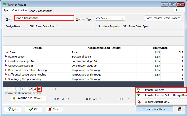
Ensure Transfer Type is set to beam and click on the left-hand span and change the Name: field in the Transfer Results form to “Span 1 Construction”.
At the bottom of the table click on the Set Default Mapping button
 to create a mapping between the analysis load results and the design beam load tables.
Create a second transfer set by clicking on the + button at the top of the form and then clicking on the right span in the graphics window.
Set the Name: for this second set to “Span 2 Construction” and then carry out the automatic mapping again.
Click on the Transfer Results button and select “Transfer All Sets” from the list.
Exit the Transfer Report form and the close the Transfer Results form and Automated Loadings form using ✓ OK.
In the Design Beams navigation window it can be seen that all the construction load cases and the differential temperature/shrinkage cases have entries for the two Inner beams.
Save the file as “My EU Example 10_1 Construction_Loads.sst”.