
Grillage Generation
A grillage refined model and 2 line beams will be defined in the same project, using the same Design Beams. One or more Line Beam models can be created automatically from the Refined Model, so we will create the Refined Model first.
(If not continuing from last section, open "EU Example 10_1 Created_Beams.sst" via Help | Tutorials | Open Tutorial Model... from the main menu.)
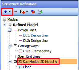
In the Structure Definition navigation window toolbar click on the Add Model button and select Refined Model.
All the material and design beams are already defined but for the grillage it is necessary to define two Design Sections, one to represent the concrete transverse diaphragm and the other to represent a nominally flexible member that will be situated along the edge of the deck.
In the Design Sections navigation window toolbar click on the
 button and select New Section | Parametric Shape to open the Define Section Element form.
Set Width to “600”, Depth to “1470” and the Property to C32/40 concrete.
The Hook Point | Reference should be set to “-1” and the Y & Z coordinates to “0” and “0”.
Close the Define Section Element form with ✓ OK.
Rename the SS1: Section to “Diaphragm” using the right mouse button menu with the "SS1: Section" node selected.
In the Design Sections navigation window click on Design Sections, at the very top, and then click on
in the toolbar to add a new parametric rectangular section.Set Width to “10”, Depth to “10” and the Property to C32/40 concrete.
The Hook Point | Reference should be set to “0” and the Y & Z coordinates to “0” and “1370”.
Close the Define Section Element form with ✓ OK.
Rename the SS2: Section to “Nominal”.
In the Structure Definition navigation window toolbar (with the "Refined Model" node selected) click on the
button and select “Design line” to open the Define Design Line form.Click the + button.
Select the Line radio button and click the “Next” button twice.
Enter (-1, 6) for the co-ordinates of point 1 and (45, 6) for point 2.
Click Next and ✓ OK twice to close all the forms.
Click on the
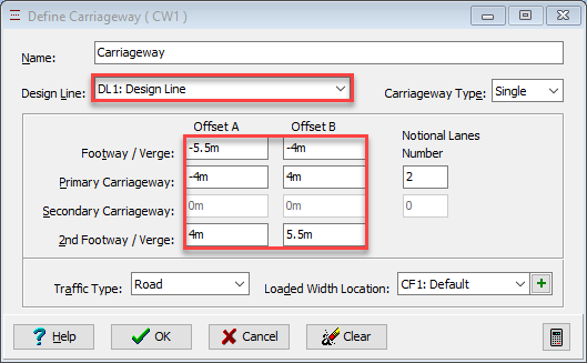
button and select “Carriageway” from the dropdown list to open the Define Carriageway form.Set the fields to the selections and values shown below. (Note that the traffic flow direction is indicated by a triangular arrow head in each notional lane and clicking on each of the arrows until they are double-headed will show that traffic can flow in either direction. However, in this example we will leave the lanes as single direction).
Click ✓ OK to close the Define Carriageway form.
Add another Design Line with the co-ordinates (0, 0) for point 1 and (2, 12) for point 2.
Click on the
button and select 2D Sub Model (GCS, Z=0) from the list to create a new sub-model.Select the sub-model, as shown below, and then click on the
 button to select Construction Lines which will open the Define Construction Lines form.
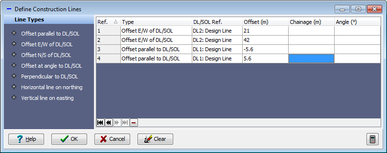
Use the Offset Line Types to enter the selections and values shown below.
Click ✓ OK on the Define Construction Lines form.
Click on the 2D Model A sub-model then click on the
button and select “Mesh” from the dropdown list. This opens the Define Mesh form.Set the Mesh Type to “Skew”.
Click on the four edges of the left-hand span, in clockwise direction, starting with the bottom edge.
Set the Longitudinal Number to “8” and the Transverse Number to “13”.
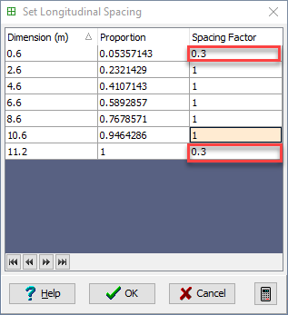
Select “set spacing” in the Longitudinal field to open the Set Longitudinal Spacing sub form.
Set the values in this sub form to those shown below.
Set Longitudinal Spacing
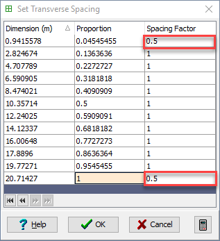
Select “set spacing” in the Transverse field to open the Set Transverse Spacing sub form.
Set the values in this sub form to those shown below.
Set Transverse Spacing
Set the Name to “Span 1” and click ✓ OK on all the forms.
Click on the 2D Model A sub-model then click on the
button and again select “Mesh” from the dropdown list.Click on the four edges of the right-hand span, in clockwise direction, starting with the bottom edge then click on the Copy Mesh Details From button and select the first mesh to give the same mesh spacing.
Set the Name to “Span 2” and close the form with ✓ OK.
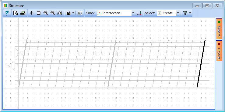
Select Refined Model at the top of the navigation window, click on the
toolbar button and select Span End Lines to open the Define Span End Lines form.Click on the bottom left and top left-hand corners of the structure on the graphics window. This will draw a heavy black line.
Repeat this for the central row of supports and the right-hand abutment to define the span end lines as shown below.
Click ✓ OK to close the form.
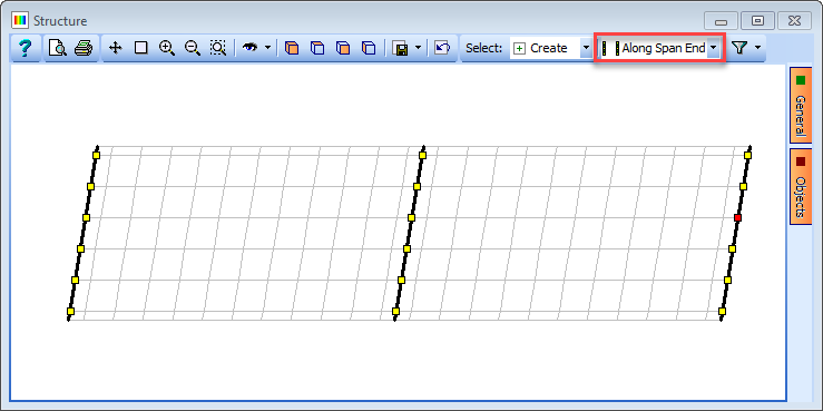
Select Refined Model at the top of the navigation window, click on the
toolbar button and select Supported Nodes.Ensure that the Select: field is set to “Along Span End Line” and select the nodes shown below.
With the Group Type set to “Uniform” set all restraints to “Free” except Direct Restraint Z, which is “Fixed”.
Now set the Group Type to “Variable” and click on the node just above the centre of the left-hand abutment.
Adjust this to be “Fixed” in the X and Y directions, then select the node just above the centre of the right-hand abutment and adjust this to be “Fixed” in the Y direction.
Click ✓ OK to close the form.
Save the file as “My EU Example 10_1 Grillage.sst”.