
Grillage Traffic Load Optimisation
(If not continuing from last section, open "EU Example 10_1 Grillage Basic Loading.sst" via Help | Tutorials | Open Tutorial Model... from the main menu.)
The next task is to create some influence surfaces and generate live load patterns using the load optimisation in the program.
The first step is to define the influence surfaces we want to generate, which are bending moment influences at each point along one inner beam in span 1.
In the main menu select Data | Influence Surface to open the Influence Surface Generation form.
Set Pick Mode to “Longitudinal Beam” then click on the inner beam located just above the centre of the deck in the left-hand span in the graphics window. This will define 13 influence surfaces for My Sagging.
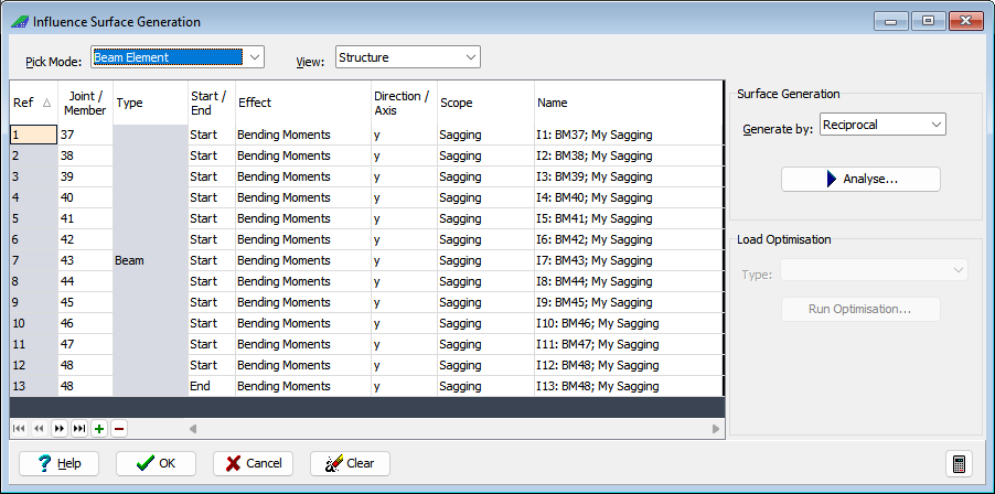
The next step is to analyse the structure to generate the influence surfaces.
Set Generate by to “Reciprocal” and click on the Analyse button. A progress box will open.
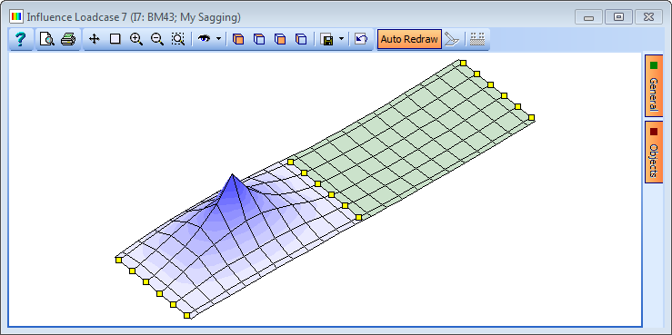
Click on the ✓ Done button when the analysis has completed. The graphics window will now show the influence surface for the first member selected.
Change the view to isometric then click the first line in the Ref column on the Influence Surface Generation form.
Use the up and down cursor keys on the keyboard to move through the influence surfaces.
For each influence surface an optimised traffic load pattern can be created for different types of Eurocode load combination. Each load pattern is defined as an ASBD load compilation.
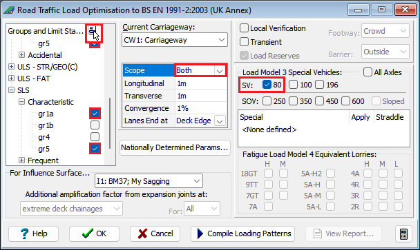
Set Type to “Road Traffic” then click on the Run Optimisation button to open the Road Traffic Load Optimisation form.
In the Groups and Limit States area click on the
 button and select “Clear All” before expanding the ULS-STR/GEO (B) and SLS Characteristic groups to select both gr1a and gr5 in each.
As the gr5 combination has been selected it is necessary to specify the type of Load Model 3 Special Vehicle(s) which in this case should be SV80 only.
Ensure that the Scope field on the Key data tab is set to “Both” to ensure both sagging and hogging load patterns are generated.
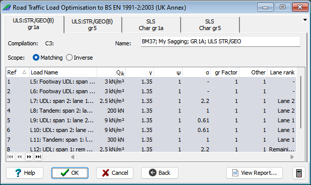
Click on the Compile Loading Patterns button to run the load optimisation.
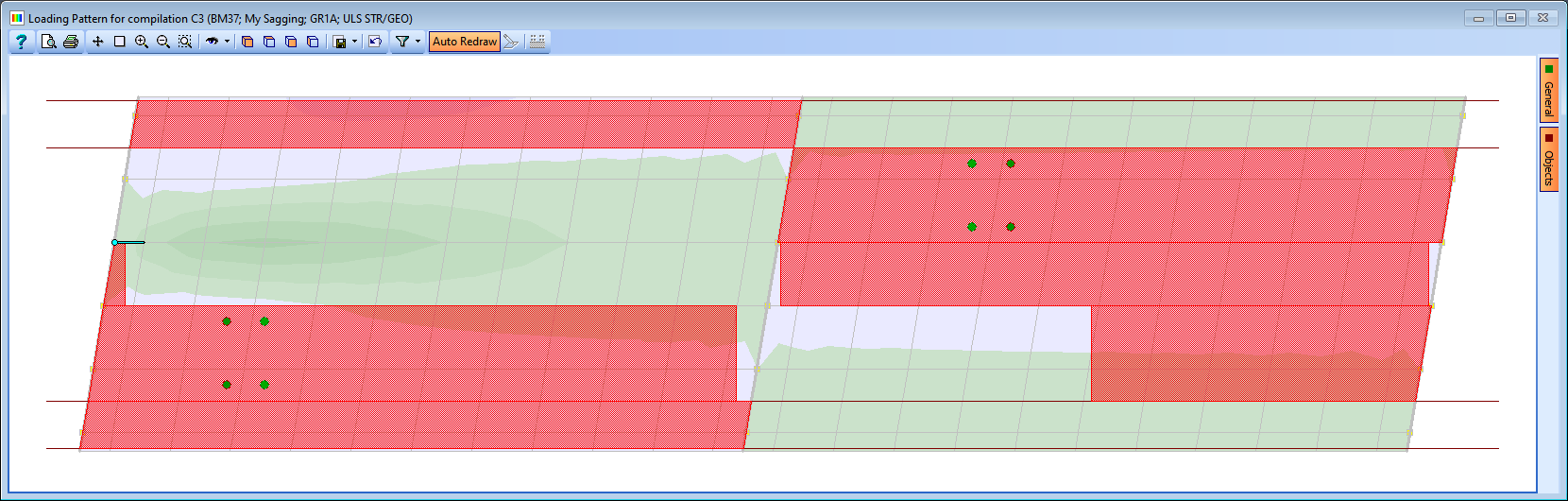
Details of the load optimisation run will be shown together with the loads created both on the form and in the graphics window. (2 notes may appear on the Results Viewer regarding the SV80 influence surface which are for information and can be ignored i.e. close the results viewer).
Use ✓ OK on the load optimisation forms to close it and save the loads and compilations that have been created.
With some small modifications the data in the influence table can be used to create influences for shear force.
In the first row of the Effect column, change “Moment” to “Shear Forces” and respond with “Yes” when asked to apply change to other beam elements.
In the first row of the Start/End column change “Start” to “End” and then delete the very last row in the table (it is not possible to use the reciprocal method for shear at nodes that are supported).
Click on the Analyse button.
Click on the Run Optimisation button to open the Road Traffic Load Optimisation form and then click on the Compile Loading Patterns button to run the load optimisation as all the parameters are the same.
In the confirmation window select “No” to deleting the previously generated loads.
Use ✓ OK on the load optimisation forms to close it and save the loads and compilations that have been created and also close the Influence Surface Generation form with ✓ OK.
Save the project file as "My EU Example 10_1 LoadOptimisation".