
Grillage Basic Loading
(If not continuing from last section, open "EU Example 10_1 Construction_Loads.sst" via Help | Tutorials | Open Tutorial Model... from the main menu.)
The next step is to apply some basic superimposed dead and live loads to our model, (the dead loads for concrete have already been input into the beam files by means of transfer from the Line Beam model).
With the Refined Model active, in the Structure Loads navigation window click on the
 toolbar button and select Bridge Deck Patch Load from the drop down list to open the Define Bridge Deck Patch Loading form.
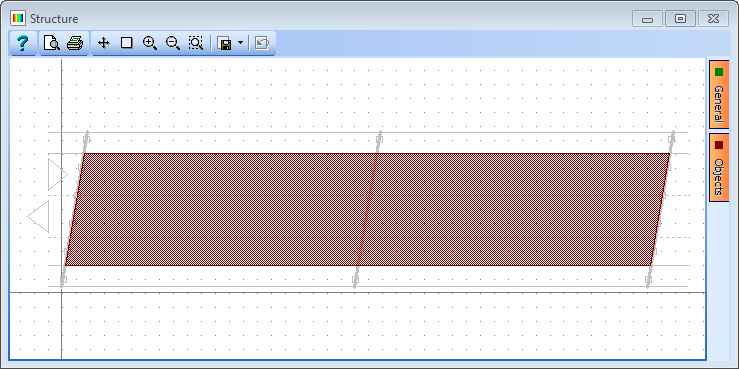
In the graphics window, click on the Objects tab and deselect “Design / Setting Out Lines”, “Construction Lines” and “Beam Elements”. The graphics now shows the carriageway and span end lines.
Click on the bottom edge of the main carriageway (it will become highlighted), the right hand span end line, the top edge of the carriageway and the left hand span end line (See following image for details of the carriageway edge locations). This will apply a patch to the carriageway.
Set Load per unit area to “2kN/m²” (press the enter key to register it).
Change Name to “SDL – Carriageway”.
Click ✓ OK to close the form.
Create a second Bridge Deck Path Load.
Click on the bottom edge of the south verge, the right hand span end line, the top edge of the south verge and the left hand span end line. This will apply a patch to the south verge.
Set the Load per unit area to “3kN/m²”.
Change Name to “SDL – South Verge” then click ✓ OK to close the form.
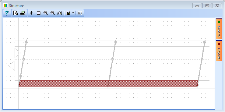
Repeat the process for the north verge to assign a Bridge Deck Patch Load of 3kN/m² as shown below.

The next step is to define an SDL barrier load.
On the graphics window, click on the Objects tab and select “Beam Elements”.
Click on the
toolbar button and select Beam Member Load | Beam Element Load from the drop down list to open the Define Beam Loading form.Add a new row using the table + button. In the new row set Load Type to “F Uniform”, Direction to “Global Z”, Load Value to “Length” and Load W1 to “-1.3kN/m”.
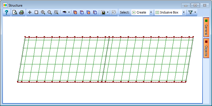
On the graphics window, click on the filter drop down and select “Longitudinal Beams”.
Draw boxes around the edge longitudinal beams to assign the loads.
Press <Ctrl-A> on the keyboard to remove the filter.
Change Name to “SDL - Barriers” and click on ✓ OK to close the Define Beam Loading form.
The next step is to create SDL compilations for ULS and SLS.
In the Structure Compilations navigation window click on the
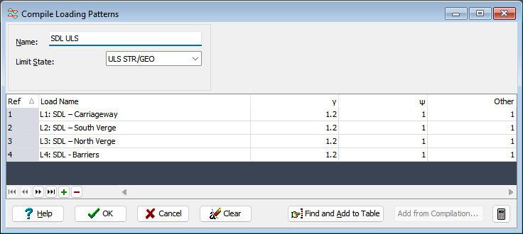
toolbar button and select Superimposed Dead Load to open the Compile Loading Patterns form.Set the Limit State field to “ULS STR/GEO” and click the Find and Add to Table button to add all the basic loads into the table.
Change the Name to “SDL ULS” and click on ✓ OK to close the form.
Right click on compilation “C1: SDL ULS” on the Navigation Pane, then select Copy to create a duplicate of the first compilation.
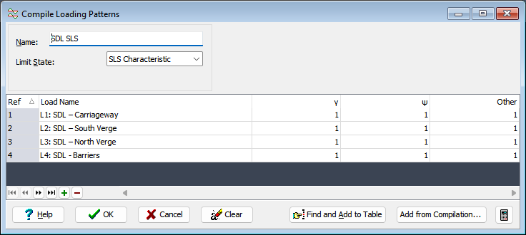
On the Compile Loading Patterns form, change Limit State to “SLS Characteristic” and click on “Yes” in the confirmation dialog to change the factors.
Change the Name to “SDL SLS” and click on ✓ OK to close the form.
Save the file as “My EU Example 10_1 Grillage Basic Loading.sst”.