
View > Appearance
Use the controls in the View > Appearance to define the model display. Several of these options are only available when results are displayed, and others are available for both setup and results views. All are presented in this topic.
Visual Style


Axes
Expand the Axes menu to toggle the display of the three coordinate axes:
a. Bounding Coordinate Axis
b. Local Coordinate Axis
c. Global Axis
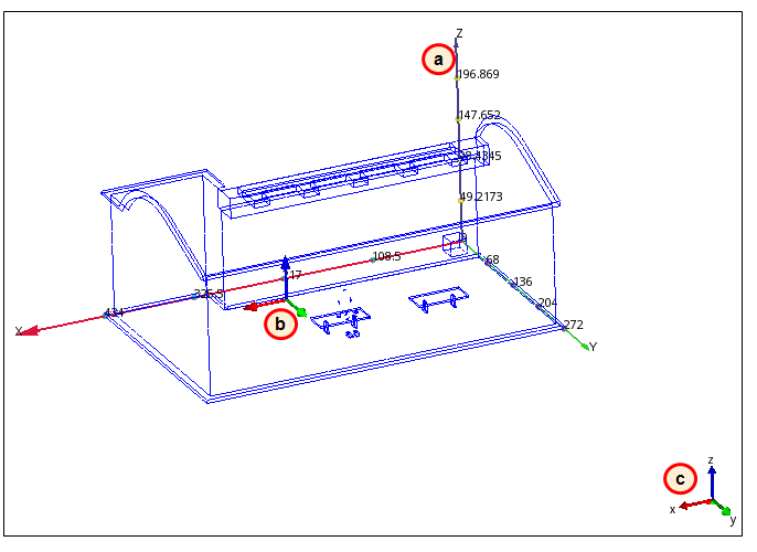
The value in the adjacent field is the number of axis increments. Change this number with the arrows to the right of the field.
Selection List
Toggle the display of the Selection List. The Selection List performs several roles, based on the active task:
Setup tasks
- The Selection List displays the names of items selected while defining the simulation model. Knowing which items are selected facilitates the setup of complex models.
Results tasks
- In the Planes and Iso Surfaces Results tasks, the Selection List lists all planes and iso surfaces, respectively.
- In the Wall Calculator, Parts, and Points Results tasks, the Selection List contains controls relevant to the current task. Note that not all of these controls are available in the ribbon context panels.
The Selection List floats, and does not have a fixed location within the Graphics window.
The Selection list toggle is also on the Quick Access toolbar:

Scale
Toggle the display of the model scale. This is useful for understanding the physical length of the model.
Perspective / Orthographic
Toggle between Orthographic and Perspective to control the depth view of the model.
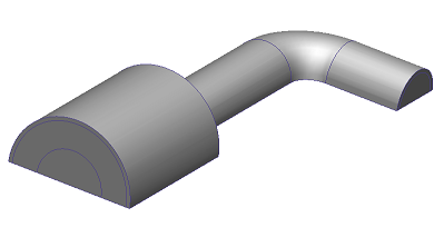
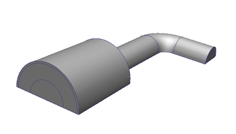
Orthographic displays model entities in their actual sizes. It is useful for making selections when the model is aligned to a Cartesian axis.
Perspective provides "depth" to the model by reducing the size of objects that are further away from the viewer. It provides a more physically realistic view.
Example showing the use of the Orthographic view...
Background
Use Background to set the color of the Graphics window. Choose from a large number of colors and color distributions.
By default, the background color is set automatically when launching from CAD (for Autodesk® Inventor, Pro/Engineer, and Solid Works). To modify this, open the Application menu (button in top left corner), and click Options. Change the Background Color from CAD Dependent to User Defined.
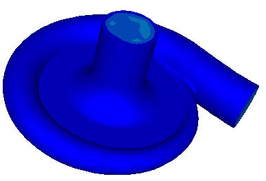
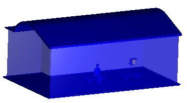
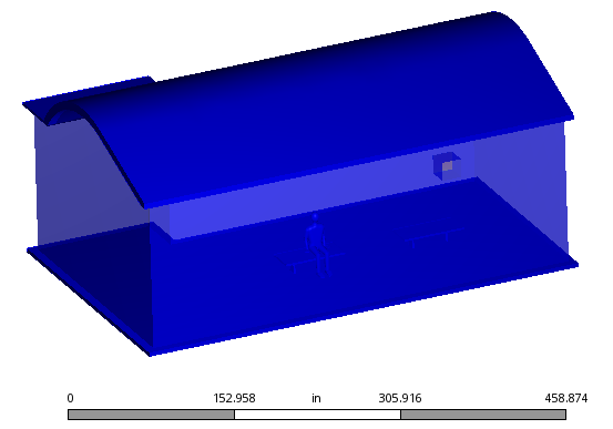
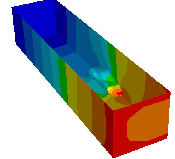
Z-Clip
Use Z Clip to view the interior of the model. Use the Front plane and Back plane sliders to control how much of the interior is visible:
If the internal model edges appear blurry, increase the Mesh factor.
To return the Z Clip plane to its default state, click Reset, or close the Z-Clip Control and Crinkle Cut dialog.
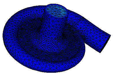
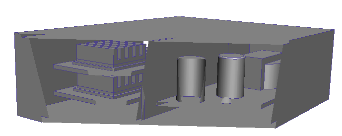
Crinkle Cut
To view the mesh on the interior of the model, check Crinkle Cut. Use this to examine the internal mesh distribution:
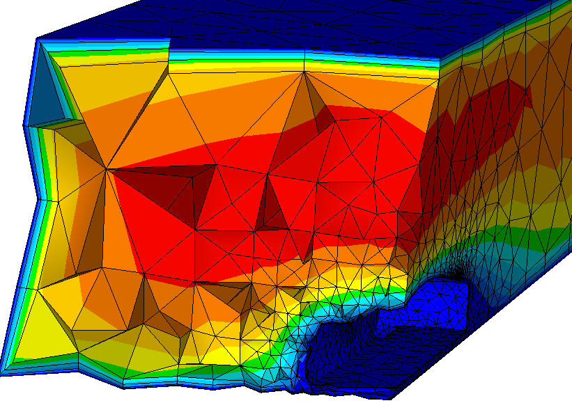
To turn off the crinkle-cut view, uncheck Crinkle cut, or close the Z-Clip Control and Crinkle Cut dialog.
Legends
By default, the results legend appears when results are displayed. To hide the legend, click Legends.
The legend size is defined by the maximum number of legends that can be stacked vertically. Control this in the field adjacent to the Legends toggle.
- To reduce the legend size, increase this value. This increases the number of legends that can be stacked vertically.
- To increase the legend size, decrease this value. This reduces the number of legends that can be stacked vertically.
For more about controlling the legend...
Surface Blanking
When viewing results, click Surface Blanking to hide surfaces instead of volumes (the default).
For more about hiding entities...
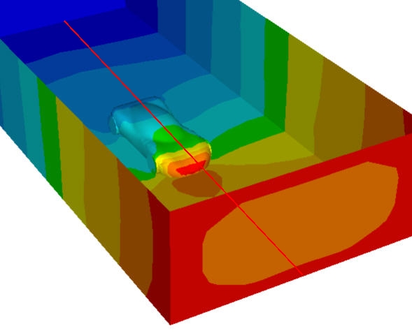
Mirror
When results are displayed, enable Mirror to reflect the model and all visualization entities about a plane. This is useful for models that have been divided by symmetry.
To activate mirroring
- Check Mirror enabled.
- If the model has been meshed, but Mirror is disabled, click the Results tab followed by the View tab.
To define the reflection plane
- Select any planar surface.
- Alternatively, click X-Y, Y-Z, or Z-X.
To disable mirroring
- Uncheck Mirror Enabled
Drop Down Menu
Click the slide-out arrow on the panel title bar to access the following controls:
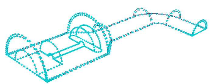
Mesh Seeds
To help define the mesh, Mesh Seeds indicate the locations of nodes when the mesh is generated. They help identify areas of the mesh distribution that need adjustment before generating the mesh. Mesh Seeds are displayed by default.
On complicated models that contain many edges, Mesh Seeds can cause slow graphics performance. To improve navigation, use Mesh Seeds to disable them.
Model Shadow
Use the Model Shadow to display a shadow below the model geometry:
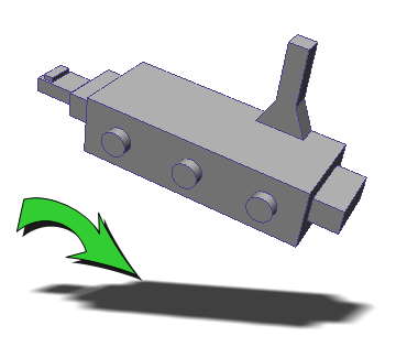
This is a useful visual accent for results presentation.
For more about modifying the mesh distribution...