Inspection results
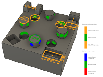
Inspection results, imported from machine-generated results files, show detailed information from measurements taken on a CNC machine. Results can include surface inspection (Inspect Surface) and geometric dimensions of critical features like holes and bosses (Probe WCS and Probe Geometry).

Example of surface inspection and geometric dimension results.
The detailed information includes nominal and measured values, calculated deviation, and error. Analysis of the deviations indicates if the measured surface, or geometric feature, is in or out of tolerance.
*.mpf, *.msr, *.dat, *.log, *.a, *.out, *.bat, and *.txt.Projection for surface inspection
Projection is a method of calculating surface inspection results when importing a machine-generated results file. By default, projection is on.
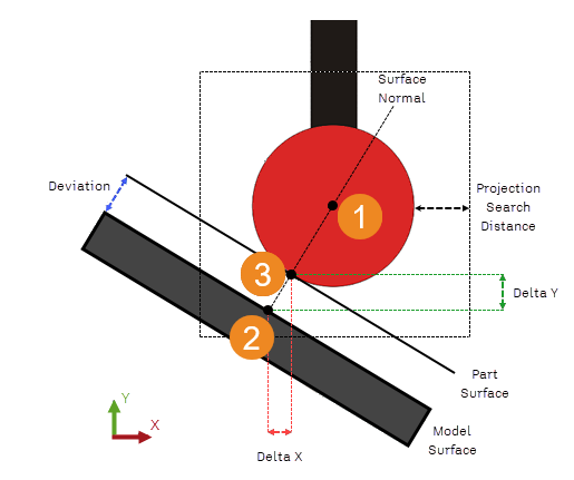
When using projection, the deviation of a point is calculated as the distance between its nearest nominal position (Projected XYZ) and the contact point on the surface of the physical part (Contact XYZ). Using projection increases the accuracy of the inspection results and is necessary when they are used to calculate a part alignment.
How projection works
A Projection Search Distance, measured from the surface of the probe's stylus tip, determines the maximum distance that a point can be from the nominal surface. If the nominal surface is not found, the contact point is not calculated, and therefore is not projected.

 The center of the probe's stylus tip. The Projection Search Distance is measured from the surface of the tip.
 The nearest nominal position on the CAD model within the Projection Search Distance, used to calculate the surface normal.
 The contact point on the physical part, found by projecting the tip radius along the surface normal. It is used to calculate the Delta XYZ and Deviation length.