Tables, balloons, and bend identifiers
In the Drawing workspace in Fusion, you can use the tools in the Tables panel on the toolbar to create tables in a drawing as you document your design. You can also add balloons or bend identifiers to label components in the design as they appear in the table.
You can use the following commands to create and modify tables, balloons, and bend identifiers on a sheet:
- Table

- Custom Table

- Parts List

- Balloon

- Bend Table

- Bend Identifier

- Hole Table

- Configuration Table

- Revision History

- Revision Marker

- Revision Cloud

- Renumber

- Align Balloons

Tables
The Table ![]() tool automatically creates a parts list or bend table, based on the contents of the current sheet, or you can select a specific table type in the dialog.
tool automatically creates a parts list or bend table, based on the contents of the current sheet, or you can select a specific table type in the dialog.
You can create the following types of tables on a sheet:
- Custom Table
- Parts List
- Bend Table
- Hole Table
- Configuration Table
- Revision History
Parts lists are created for component, assembly, and animation references. Bend tables are created for sheet metal flat pattern references.
Shift key.Custom Tables
The Custom Table ![]() tool creates a table with empty cells that you manually populate.
tool creates a table with empty cells that you manually populate.
You place the table on the sheet, then adjust the table direction, text alignment, number of columns, and number of rows.
Parts Lists
The Parts List ![]() tool creates a table that automatically populates cells with information about an assembly, storyboard, component, or sheet metal component reference.
tool creates a table that automatically populates cells with information about an assembly, storyboard, component, or sheet metal component reference.
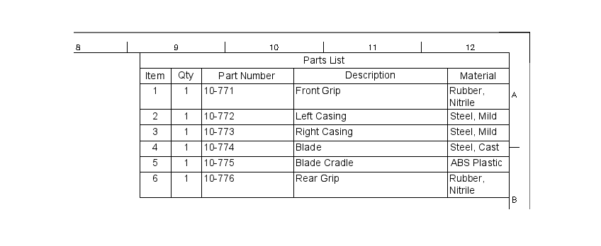
A Parts List is a table that itemizes the components in a design. Each row can include the following information about a component:
- Item
- Qty
- Part Number
- Part Name
- Description
- Material
- Mass
You select a view, select the structure, place the table on the sheet, then adjust the table direction and columns. Balloons are automatically added to associated views.
Structure
When you create a parts list, you can select from 2 Structure settings:
- First Level: Includes only the first level of sub-components in the parts list.
- All Level: Includes all components in the parts list.
Component properties
You can modify the part number and description of a component in the Design workspace. In the Browser, right-click the component, select properties, and edit the values in the Properties dialog.
If you change the properties of a component in the Design workspace, the changes are applied to the parts list the next time you update the drawing. Item numbers are assigned to components in the order in which they were created.
Suppress components
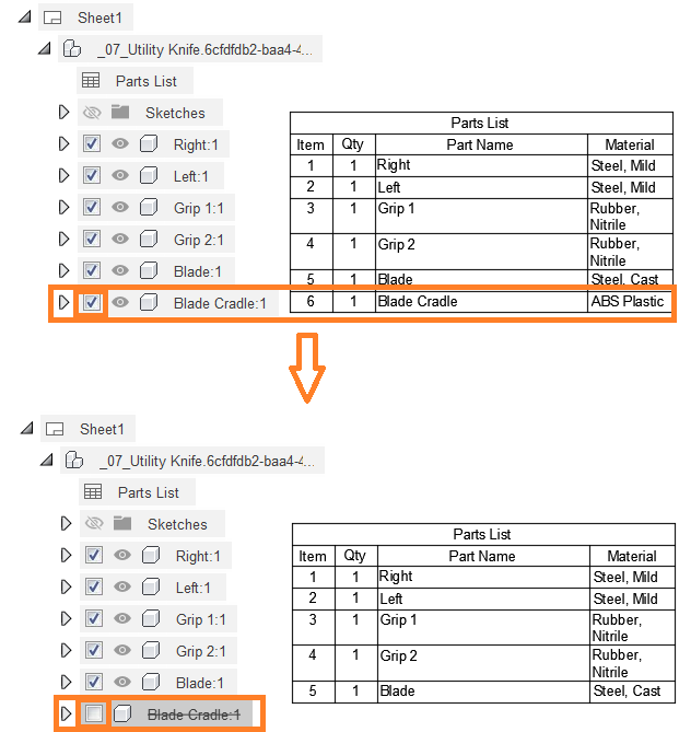
You can suppress components to remove them from the parts list. In the Drawing workspace, locate the component in the Browser, then uncheck the Suppress box to suppress the component. The component is hidden from the associated views and removed from the parts list.
Balloons
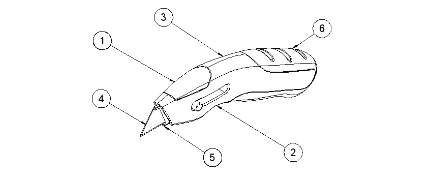
The Balloon ![]() tool creates balloons to identify components in an assembly as they appear in a parts list.
tool creates balloons to identify components in an assembly as they appear in a parts list.
You can create 2 types of balloons:
 Standard: Leaders with straight lines
 Patent: Leaders with curved splines
Bend Tables
The Bend Table ![]() tool creates a table that automatically populates cells with information about each sheet metal bend in a flat pattern reference.
tool creates a table that automatically populates cells with information about each sheet metal bend in a flat pattern reference.
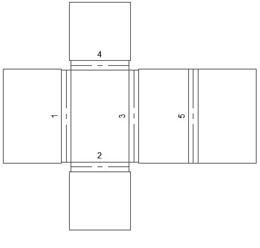
You select a flat pattern view, then place the bend table on the sheet. Bend identifiers are automatically added to the view.
Bend Identifiers
The Bend Identifier ![]() tool creates bend identifier labels to identify the centerlines of sheet metal bends in a flat pattern as they appear in a bend table.
tool creates bend identifier labels to identify the centerlines of sheet metal bends in a flat pattern as they appear in a bend table.
Hole Table
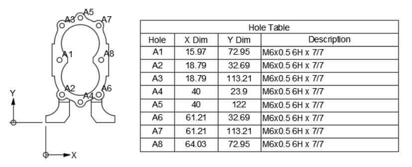
The Hole Table ![]() tool creates a table that automatically populates cells with information about each hole in a view.
tool creates a table that automatically populates cells with information about each hole in a view.
Hole tables follow the drawing standard you’ve selected and populate the appropriate dimensions and standard of annotation.
Hole tables require an origin. You can either place a new one when the Hole Table tool asks you to, or it can be an existing origin that was placed with ordinate dimensions. Each view require its own origin.
Configuration Table
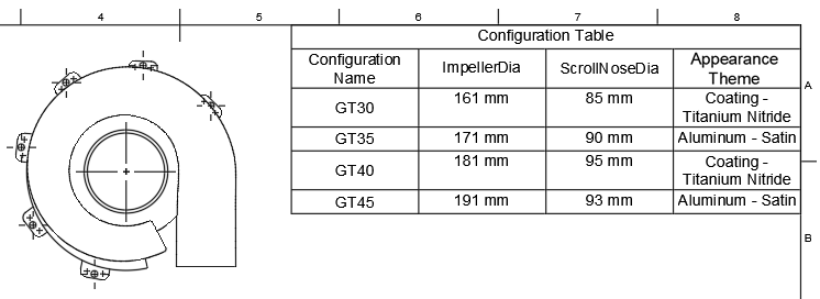
The Configuration Table tool ![]() creates a table that displays configuration data from a configured design on a sheet to create a tabulated drawing.
creates a table that displays configuration data from a configured design on a sheet to create a tabulated drawing.
Add the following configured aspects from the design configuration table:
- User Parameters
- Feature Parameters
- Physical Material
- Appearance
- Sheet Metal Rules
- Plastic Rules
Revision History
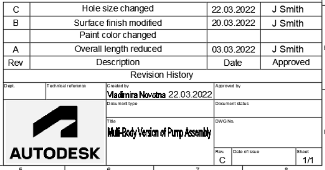
The Revision History ![]() tool creates a history revision table for the active sheet.
tool creates a history revision table for the active sheet.
Revision Marker
The Revision Marker ![]() tool creates non-associative and associative revision markers with and without a leader.
tool creates non-associative and associative revision markers with and without a leader.
Revision Cloud
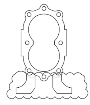
The Revision Cloud ![]() tool creates closed polylines that form cloud-shaped objects consisting of arc segments.
tool creates closed polylines that form cloud-shaped objects consisting of arc segments.
You can use revision clouds to call attention to specific changes or portions of each drawing.
Renumber
The Renumber ![]() tool renumbers balloons on a sheet.
tool renumbers balloons on a sheet.
Align Balloons
The Align Balloons ![]() tool aligns balloons on a sheet.
tool aligns balloons on a sheet.