
Analyze multiple geometries on the same build plate.
Video length (4:08).
Follow the step-by-step instructions shown in the video.
Sample files for use with the tutorials are available from the Downloads page. Expand the downloaded ZIP archive into a convenient directory from which you can import files into Local Simulation as you need them.
- Click .
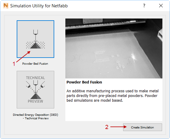
- In the dialog that opens, click
Powder Bed Fusion and then
Create Simulation.
- In the
Import Model dialog, browse to the sample files subfolder Example_8, and open
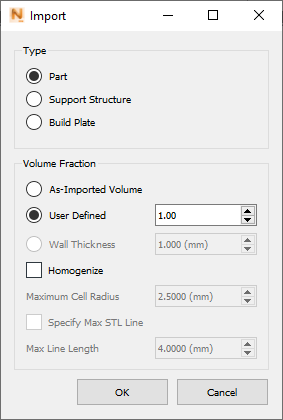
part1.stl. In the
Import dialog, specify that this is a part, not a support structure.
You will open three more files from this folder.
- Click
, and open the file
part2.stl, again specifying it as a part.
The build plate expands to accommodate both parts.
- Open support1.stl. In the Import dialog, select Support Structure, and set the Volume Fraction to 0.3.
- Open support2.stl. In the Import dialog, select Support Structure, and set the Volume Fraction to 1.0.
- Click
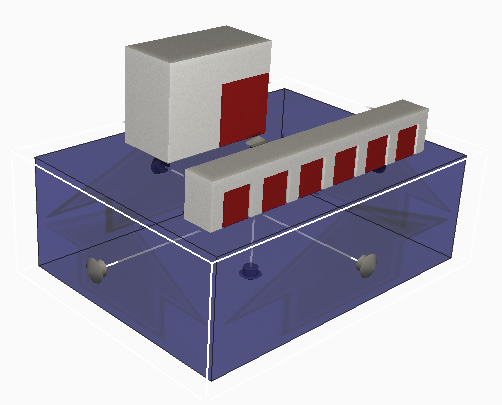
 and expand the build plate in X and Y directions to be a bit wider than the parts. You can use the handles shown in the figure, or change the
Length values for X and Y on the Size tab.
and expand the build plate in X and Y directions to be a bit wider than the parts. You can use the handles shown in the figure, or change the
Length values for X and Y on the Size tab.
- Click
and save the project.

Note how the size of the mesh elements varies by location. This shows the adaptive meshing strategy, which decreases the number of degrees of freedom required to solve the problem.
- Click Solve to run the simulation, and load the results.
- Click
.
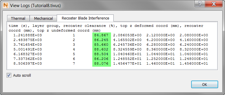
Note the high values for recoater clearance (highlighted), indicating that the support structures were keeping distortion to low levels. The default value for Recoater tolerance is 80%. Recoater tolerance is a user-defined value, set in the Solver Settings dialog, which specifies how much risk is accepted when predicting possible recoater interference. The lower the value, the higher the threshold is for issuing a recoater warning. Higher values will issue more recoater warnings. Consult the Recoater Tolerance page for further information.
- In the Browser, in the Results section, turn off
Geometry, turn on
Structure type and play the animation to near the end.
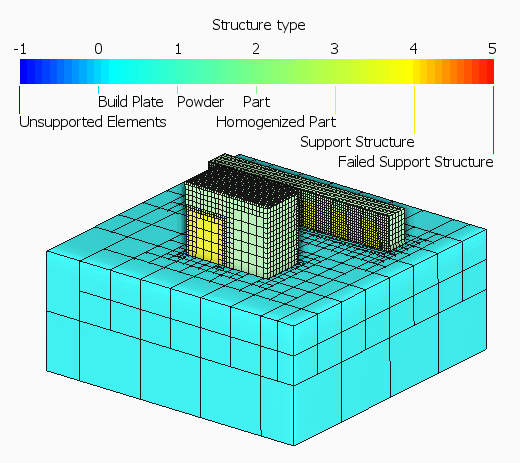
Here you can see that the build plate, parts, and support structures are clearly marked.
- In the Browser Results, turn on Displacement and play through the animation.
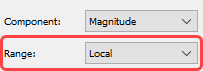
- In the
Results Settings panel, ensure that the
Range setting is
Local.
Playing through the results shows the development of distortion during powder bed processing.
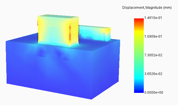
For a clearer display, as shown, you may want to turn off Element Edges in the Browser Results.