
Use Circle: N Points to construct a circle running through the centres of specified features on a part. Use this item to check the diameter and form of a circle constructed from three or more items in the inspection sequence.
To create a Circle: N Points item:
- Open a Geometric group in the Sequence Tree.
- Click Geometry tab > Features panel > Circles > Circle: N Points.
The Circle: N Points dialog contains the following areas:
Name — Enter a name for the item. The name is used in the inspection sequence, in the Report and Info tabs, and when referencing the item in other items.
Use nominals — Select this check box to enter or change the item nominals, and to compare the item measurements to their nominal values. Deselect this check box to disable comparisons with the item nominals.
When this check box is selected, an in-tolerance
 or out-of-tolerance
 indicator is displayed on the measured item's icon in the inspection sequence; the border of the item
label is coloured to indicate whether the measurements are within tolerance; and the tolerance, nominal, deviation, and error values of the item are shown in the report.
indicator is displayed on the measured item's icon in the inspection sequence; the border of the item
label is coloured to indicate whether the measurements are within tolerance; and the tolerance, nominal, deviation, and error values of the item are shown in the report.
When this check box is deselected, the Nominal boxes are disabled, no tolerance indicators are displayed and no tolerance, nominal, deviation, and error values are shown in the report for this item.
 and select
From CAD Entity. To replace the nominals with the item's measurements in the current Measure, click the button and select
From Active Measure.
and select
From CAD Entity. To replace the nominals with the item's measurements in the current Measure, click the button and select
From Active Measure.
Visible — Select this check box to display the item in the CAD view.
Output in report — Select this check box to include the item in the report.
Coordinate system — Select the alignment relative to which the item's measurements are to be reported.
To specify the alignment during the inspection, select <Active Alignment>. You can then select the alignment from the Active alignment list, or by adding an Active Alignment item to the inspection sequence.
Fitting algorithm — Select the algorithm used to create the circle. Select:
- Least square to create the feature that minimizes the deviation across all probed points.
- Maximum inscribed to create the largest feature that fits within the probed points.
- Minimum circumscribed to create the smallest feature that fits around the outside of the probed points.
- Minimax to create the feature by averaging the maximum inscribed and minimum circumscribed features that have the same centre.
Reference plane — Select the plane on which you want to construct the circle.
 to
to
Reference points — Add three or more points to the Selected items list to determine the circumference of the circle.
Centre — Enter the nominal and tolerances for the position of the circle centre.
Diameter — Enter the nominal and tolerances for the Radius or Diameter of the circle.
Circularity — Enter the Maximum acceptable difference between the points with greatest positive deviation and greatest negative deviation from the best-fit circle. If the difference between the greatest positive deviation and greatest negative deviation exceeds the Maximum value, the circularity is out-of-tolerance.
To measure circularity, PowerInspect calculates the best-fit circle, C1, through the points. It then runs two concentric circles through the points furthest from the new circle in each direction, shown as C2 and C3:
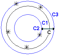
The Circularity value is the difference between the radii of C2 and C3.
Click OK to close the dialog and save your changes.