The next stage involves selecting a tool and defining its geometry. This example uses a 16 mm (5/8 inch) tip-radiused tool.
- In the Model Area Clearance strategy dialog, click
 to display the Tool page.
 - On the Tool page:
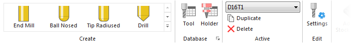
- Click the
 arrow next to the Create Tool
  button in the Tool area.
 - From the tool list, select
 to create a Tip Radiused Tool.
- Click the
- On the Tool page, click
 to display the Tip Radiused Tool dialog.
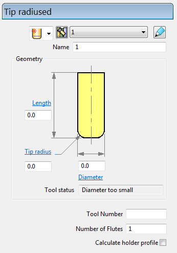
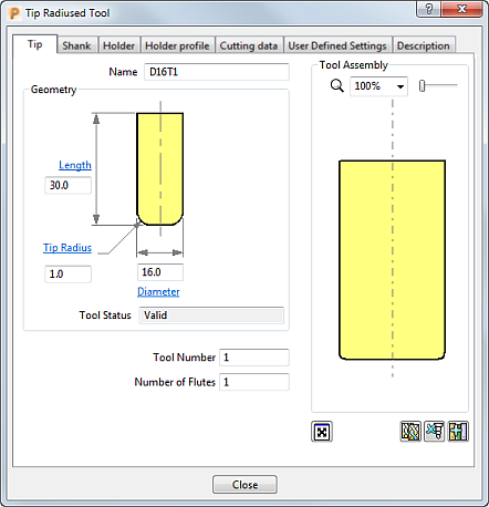
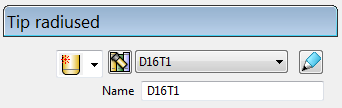
- In the Tip Radiused Tool dialog, enter:
- Name: D16T1
- Length: 30 mm
- Tip Radius: 1 mm
- Diameter : 16 mm
- Tool Number : 1
- Select the Shank tab, click
 to add a shank component. Enter:
- Upper Diameter : 16 mm
- Length: 70 mm
The Lower Diameter automatically defaults to the Upper Diameter. This can be accepted for the current tool.
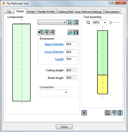
- Click Close.
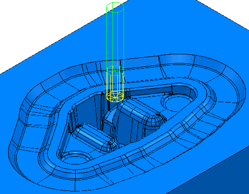
The tool is automatically aligned with the Z axis:
You can view and edit the created tool:
- In the Explorer, expand
 to see the tool you have created. Expand the tool node to see the tool's specific details.
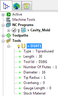
- In the Tool tab on the Model Area Clearance dialog:
- On the Tool tab: