
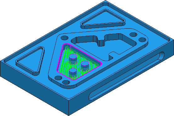
Use the Feature Area Clearance strategy to rapidly remove material from a 2.5D part. Offset toolpaths work well in the bottom of pockets whereas raster toolpaths are often used on open parts. Vortex machining enables you to increase the feed rate whilst maintaining surface quality and tool life.
Note: Feature area clearance machines the active feature group.
There are several pages associated with the Feature Area Clearance strategy:
- Feature area clearance — The main page used to choose the area clearance styles and associated settings.
- Raster — Settings to define a raster area clearance style. This page is available when you select a Style of Raster on the main page.
- Offset — Settings to define offset area clearance styles. This page is available when you select a Style of Offset model or Offset all on the main page.
- Vortex — Settings to define a Vortex area clearance style. This page is available when you select a Style of Vortex on the main page.
- Step cutting — Settings to define in-line rest roughing. This minimises terracing when creating area clearance toolpaths with a large stepdown. This is available when you select a Stepdown of Automatic.
- Finishing — Settings to perform a Final Stepover and a Final Stepdown which are different from the normal stepover and stepdown.
- Unsafe segment removal — Settings to remove small toolpath segments.
- High speed — Settings for the smoothing options to avoid sharp changes in tool direction when high speed machining.
- Order — Settings to control the order of machining.
- Approach — Settings to control how the tool approaches the path.
- Automatic verification — Settings to automatically verify toolpaths on creation.
The remaining pages are common toolpath strategy pages.