Standard results in injection molding simulation
Standard injection molding results are generated throughout the analysis and you can view them as soon as they become available, even if the analysis is not complete. Standard results are found in the Fill + Pack or Warp nodes of the Results browser.
- Results in the Fill + Pack node of the browser provide you with data such as how the plastic flows through the cavity, the temperature of the flow at various times, where plastic is solidying, where flow fronts meet, where sink marks are likely to occur, how long it takes for the plastic to cool to ejection temperature, etc.
- Results in the Warp node of the browser provide you with information about how the plastic is likely to shrink as it cools down to room temperature, and how the part might warp as a consequence.
| Result name | Example | Shows... | Access |
|---|---|---|---|
| Air traps | 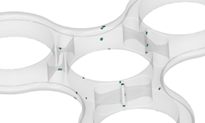 |
The location and likelihood of trapped air when the plastic flow fronts converge from different directions. Air traps may cause surface defects and incomplete filling and can be prevented with sufficient venting. | Browser |
| Avg. temperature (end of fill) | 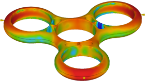 |
The average temperature through the thickness of the part at the end of fill. Too low temperature may cause filling problems, and excessive temperatures may cause longer cooling times. | Browser |
| Deflection (all effects) | 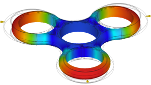 |
The final shape that results from a combination of shrinkage and warpage of the part. Warpage is caused by variations in shrinkage and influenced by part design, process settings, and material. | Browser |
| Fill animation | 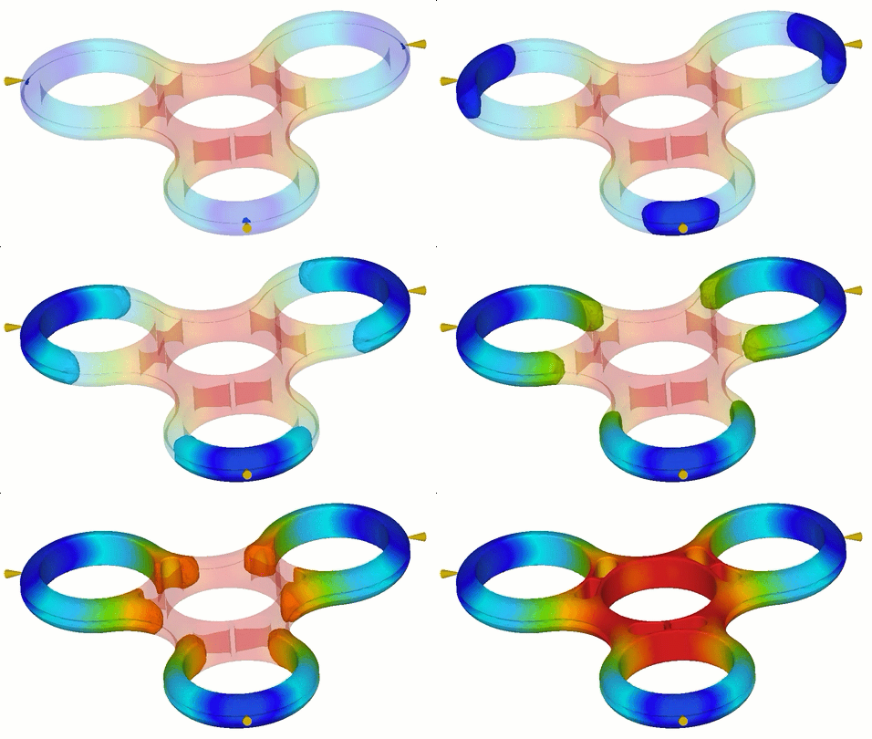 |
The progression of the plastic as it fills the mold cavity, which affects part quality. Check for unfilled areas, weld lines, and air traps. | Browser |
| Fill confidence | 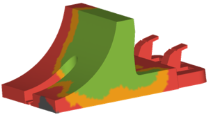 |
How easily the part will fill. Try to reduce orange and red areas to reduce the risk of incomplete filling (short shot). | Browser |
| Filled from injection location | 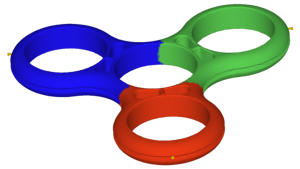 |
Which gate the material is coming, for a part with multiple gates. Check for unequal distribution of colors which indicates non-uniform filling. | Browser |
| Flow front temperature | 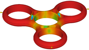 |
The temperature of the plastic flow front when it reaches any given area. To avoid quality problems, aim to keep the temperature variation within 2-5°C. | Browser |
| Injection pressure | 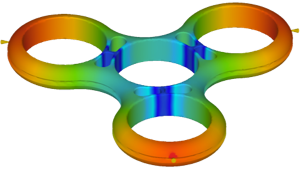 |
The pressure required to push the plastic from the injection location into the part. The injection pressure should not exceed 50% of the machine's injection pressure capacity which is 90 MPa for the default machine. | Browser |
| Quality prediction | 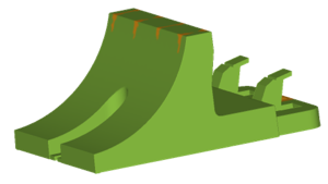 |
How well the part can be molded and where problems might occur. Try to reduce orange and red areas to reduce the risk of quality problems. | Browser |
| Sink mark depth | 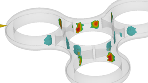 |
The presence and location of depressions on a surface, which will result in visual defects. Sink marks are typically caused by features on the opposite face of the surface. | Browser |
| Solidified plastic (end of fill) | 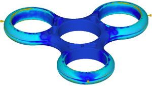 |
How much of the plastic cross-section has solidified at the end of the filling phase, which can affect warpage. The part should be less than 25% frozen at the end of fill. | Browser |
| Solidified plastic (ejection) | 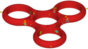 |
How much of the plastic cross-section has solidified at the time of ejection. The amount of solidification can affect warpage and, ideally, the part should be at least 80% solidified at ejection. | Browser |
| Time to ejection temperature | 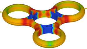 |
The time required for the plastic to freeze sufficiently for ejection. Look for areas that have significantly longer ejection time. Minimize time variation across the part. | Browser |
| Volumetric shrinkage (ejection) | 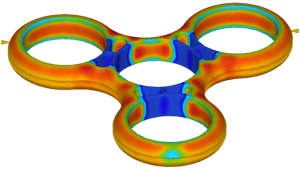 |
The distribution of volume reduction that occurs when the plastic solidifies, as a percentage. Minimize the shrinkage variation to reduce the warpage risk. | Browser |
| Warpage tolerance | 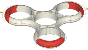 |
Where the part warpage exceeds the tolerance threshold (in red). Warpage is caused by variations in shrinkage and influenced by part design and process settings. | Browser |
| Weld lines | 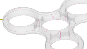 |
Where two flow fronts meet. Weld lines may create weak spots and/or visual defects. Avoid weld lines on aesthetic faces or areas that require high strength. | Browser |