
 Feature Modifier
![]() +
+ ![]() +
+ ![]()
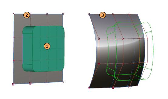
This tool takes a source object, either curves or surfaces, and makes one or more deformed copies based on the difference in shape and CV distribution between a source surface and a target surface(s).

The source object is the geometry to be copied and placed.
The source and target references are either a single curve or surface, or a group of tangent continuous curves and surfaces. Ideally the source and target references will have a similar parameterization. The U and V directions of the source and target references affect the orientation of the result, but this can be adjusted in 90 degree increments using the Rotation buttons.
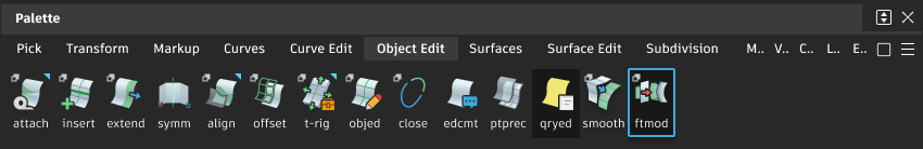
Access the tool from the Object Edit Palette:
Feature Modifier settings
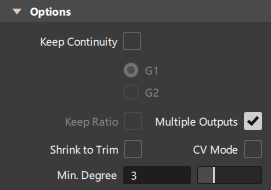
Options
Keep Continuity
The Feature Modifier evaluates the input source topology and determines the continuity at surface boundaries.
When the geometry is then copied and transformed:
- If the source reference and target reference surfaces define a simple positional or scale transformation, then continuity is likely to be maintained.
- If there is a shape difference between the source reference and target reference surfaces, then continuity is harder to achieve as the distortions of the surface patches will be greater.
Selecting Keep Continuity On will evaluate the resulting surfaces, and if continuity fails, then further calculation will be attempted to improve the results.
G1 - attempt to maintain better G1 continuity between patches. Use alongside the Minimum degree slider to attempt to achieve improved continuity.
G2 - this is more complex to achieve when large distortions have been specified, and when surfaces patches have continuity requirements on all four sides.
Selecting G2 may result in unacceptable CV distortions when unsuccessful.
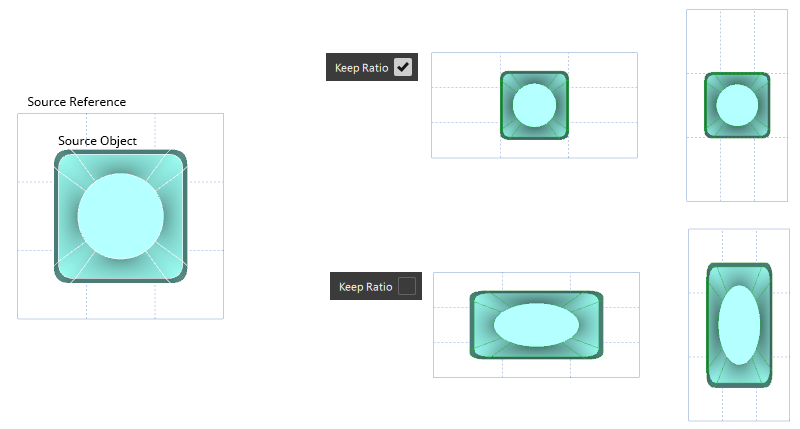
Keep Ratio
If the source and target surfaces are not in proportion to each other, then by default, the source objects will be deformed to match the target.
Selecting Keep Ratio overrides this and maintains the original proportions of the source geometry.
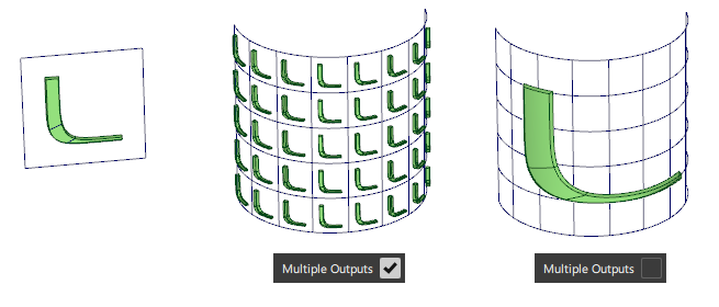
Multiple Outputs
![]()
This setting applies when multiple, tangent continuous surfaces or curves are selected for the Target Reference.
- On: The source object is applied to each separate surface or curve selected for the Target Reference. This is the default setting.
- Off: The Target References are treated as a single curve chain or surface quilt.
- For surfaces, the U and V directions of each surface need to be coordinated and the CV positions need to be in line to create well ordered flow of CVs and unified boundaries.
- For curves, the U-direction of the curves must be unified.
Shrink to Trim
Selecting Shrink to Trim on modifies surfaces to their minimum size required to maintain the trim areas.
CV Mode
The structure and parameterization of the original surface is used as input. Each CV is moved in a certain local offset direction as far as required to get the most accurate result.
CV Mode calculates more quickly and so is useful for quick iterations.
Continuity is likely to be harder to achieve using CV mode, in which case turn the option off once the final placement has been determined.
Min. Degree
Increasing the Min. degree will add CVs to low degree surfaces in order to improve the resulting continuity in the modified surfaces.
In practice this has the most influence over the resulting continuity.
Transform Options
![]()
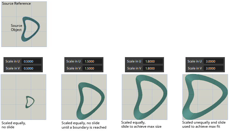
Scale in U/V
Scales the output geometry. The slider scale is 0.001 - 3.0, with a value of 1.0 representing an unchanged scale. Larger values can be entered in the number field, but will have no effect if the objects have reached the maximum size of the target surface.
The maximum size is determined by the target placement surface size and the source object bounding box.
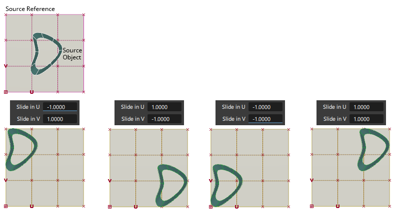
Slide in U/V
Moves the output geometry on the target surface in a range of -1 to +1, with a value of 0 being an unchanged position.
Lock Scale/Slide Controls
Locks the two U and V sliders so that they maintain the same value.
Mirror
![]()
Lets you mirror the source reference geometry, which changes the direction of the geometry on the target. Use this option in combination with Flip Side to achieve the desired orientation of the target reference.
Rotation
![]()
The two buttons +90 deg and -90 deg can be used to rotate the target geometry in 90 increments.
This is useful if the U and V directions of the source and target references are not matched. The desired result can be achieved without having to change the U or V directions on the references.
Flip Side
![]()
Places the geometry on the opposite normal direction.
By default, the geometry is placed on the target reference on the same geometric normal direction as the source reference. Flip Side uses the opposite normal direction instead.
Reset All
Returns all settings to default.
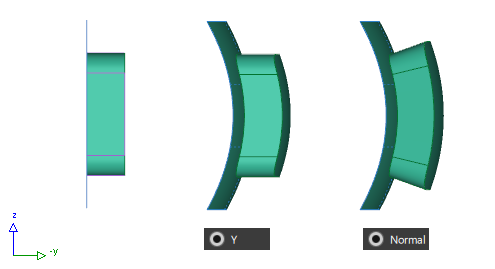
Vector Options
The vector direction selected will affect the distortion of the surfaces away from the target reference surface.
Feature Modifier workflows
Selection Order
The space bar (shortcut for the in-scene buttons) is useful in the selection sequence for Feature Modifier:
Select or box select the Source Objects
Then press spacebar
Select the Source References
Then press spacebar
Select the Target References and the modified copy will be created.
Selecting Multiple Targets
If targets are selected with a drag-select or one after another within the same execution of the tool, they are all connected with the same construction history to the source objects and the tool settings.
Feature Modifier common parameters
Feature Modifier has the following Surface Tool Common Parameters sections:
- Vector Options
- Control Options