Use the Raster page to specify settings for a raster-style area clearance strategy, which creates cutting moves at a specified angle to either the X or Y axis.
Fixed direction — Select to enable the Angle option. When deselected, PartMaker determines the most suitable angle for each area in turn.
Angle — Enter the angle to be used for all the raster passes.
For example:
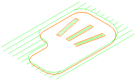
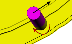
Select Fixed direction
Enter an Angle of 0
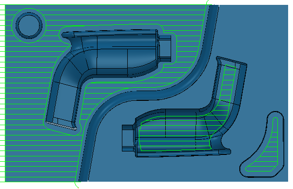
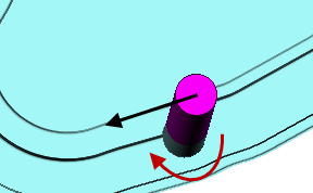
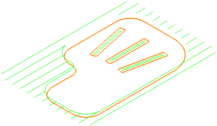
Select Fixed direction
Enter an Angle of 30
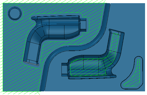
Deselect Fixed direction
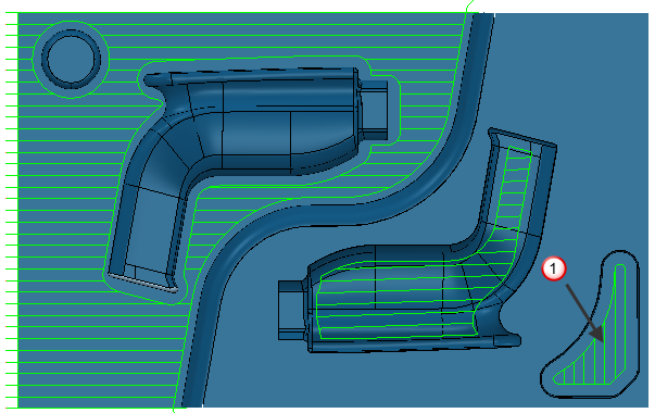
In this case, most of the toolpath has an Angle of 0, but pocket  has an Angle of 90.
Cut direction — Select a milling style for Profile and Area.
- Climb — Select to create toolpaths using only climb milling, where possible. The tool is on the left of the machined edge when viewed in the direction of tool travel.
- Conventional — Select to create toolpaths using only conventional or upcut milling, where possible. The tool is on the right of the machined edge when viewed in the direction of tool travel.
- Any — Select to create toolpaths using both conventional and climb milling, as appropriate. This minimizes the tool lifts and tool travel.
Minimize full width cuts — Select to remove (as far as is possible) all raster moves that could cause the tool to cut on its full width. Due to the searching nature of the raster pattern, the tool may occasionally be cutting on its full width. This is not generally a problem when cutting soft material, but can cause tool damage when machining hard material.
Machine all raster spans — Select to machine all raster spans. When deselected, unnecessary raster spans are left unmachined. For high speed machining, it is best to have this option selected to ensure an even loading on the tool.
An unnecessary raster span is one where the tool either doesn't remove any material or doesn't remove any material that a future pass would not remove. This can happen on the first and possibly the last raster span of an area, and where the raster spans are shorter than the diameter of the tool.
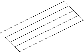
Maintain constant stepover — Select to ensurethe stepover within an area remains constant (so that cutter passes lie on both edges of each area).
- Selected
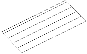
- Deselected:
Profiling — This enables profile moves to guide the tool around the profile at the cutting feed rate.
When — Select when profile moves are performed in relation to the area cutter moves.
- None — Selecting this option machines the first offset profile, then moves inwards to clear the remaining area. The workpiece profile is not machined.
- Before — When selected, the tool profiles the workpiece first and then moves inwards to clear the remaining area. This involves two cutter moves with associated rapid and level moves.
- During — When selected, PartMaker automatically chooses to apply the behaviour of the Before or After options depending on the position of the outer profile relative to the block boundary. If the outer profile lies entirely on the block boundary, PartMaker uses the Before option. If any part of the outer profile touches the workpiece, PartMaker uses the After option. There is no Z lift between area clearance and profile moves.
- After — Selecting this option machines the innermost profile first, then moves outwards to clear the area, then finally machines the workpiece profile. This also involves two cutter moves with associated rapid and level moves.