
The Process Table contains all the cutting processes required to machine the part. If required, you can also add Material Control Processes (MCPs), which control the transfer and handling of parts during machining, to the Process Table.
In PartMaker/SwissCAM, the Process Table contains the following:
Process Table toolbar
Use the Process Table toolbar to perform actions on the processes in the Process Table.
The following buttons are available in PartMaker/SwissCAM and Turn-Mill:
 — Displays the
Simulation window, where you can visualize the part being machined and identify any errors before machining.
— Displays the
Simulation window, where you can visualize the part being machined and identify any errors before machining.
 — Displays the
Tool Assembly dialog, which lists all the tools used by the processes in the Process Table.
— Displays the
Tool Assembly dialog, which lists all the tools used by the processes in the Process Table.
 — Displays the
Material Control Process Parameters dialog, which enables you to insert a material control process into the Process Table.
— Displays the
Material Control Process Parameters dialog, which enables you to insert a material control process into the Process Table.
 — Click
 to display options for controling the display of columns:
- Full View — Select to display equally spaced columns using all the available space.
- Default View— Select to position the columns in their default positions.
 — Click
to display options for the
Status column in the Process Table. When the
Status option is selected for a process,
PartMaker includes the process in simulation and postprocessing.
— Click
to display options for the
Status column in the Process Table. When the
Status option is selected for a process,
PartMaker includes the process in simulation and postprocessing.
- Show Process Status/Hide Process Status — Select to show or hide the Status column in the Process Table.
- Enable All Processes — Select to enable the Status option for all processes.
- Disable All Processes — Select to disable the Status option for all processes.
 — Displays a graphical representation, known as a Time Chart, of how processes in the Process Table are synchronized.
 — Groups consecutive processes that are machined using the same Synchronization Mode into Synchronization Groups. For Swiss machining, you can use Synchronization Groups to machine two or more processes simultaneously on different tool posts and/or different spindles.
 Window Position — Set the position of the Process Table window:
- Float — Select to open this window as a separate instance so it is not limited to within the PartMaker window and can be moved between monitors.
- Dock — Select to keep this window within the main PartMaker window.
Process details
The Process Table displays the following details about the processes in the table:
Tool button (for example,
 ) — The type of tool used to machine the process. Click the button to display theEdit Tool dialog, where you can view or edit details of the tool.
Proc ID —The process's unique identifier (ID).
Tool ID — The ID of the tool used to machine the process.
Tool No — The number of the tool used to machine the process.
Tool Name — The name of the tool used to machine the process.
Group — The name of the Group that contains the toolpath for this process.
Face — The name of the Face window that contains the Group for this process.
Feed — The feed rate used to machine the process.
Speed — The spindle speed used to machine the process.
Time — The time it takes to perform the process on the machine.
Status — When the Status option is selected for a process, PartMaker includes the process in simulation and in postprocessing.
You can select or deselect individual processes by clicking the Status check box for that process.
To enable or disable the Status option for all processes in the table, click
on the Process Table toolbar:
- Select Enable All Processes to select the Status option for all processes in the table.
- Select Disable All Processes to de-select the Status option for all processes in the table.
PartMaker uses a strikethrough to denote processes that are excluded from simulation and postprocessing. For example:

Mode — The Synchronization Mode used to machine the process.
Set Modes — Click this button to display the Set Modes dialog, where you can select the Synchronization Mode for the process.
The icon on the
Set Modes button reflects the Synchronization Mode selected for the process. For example, when the main spindle and the sub-spindle are each machining with one tool the icon changes to:

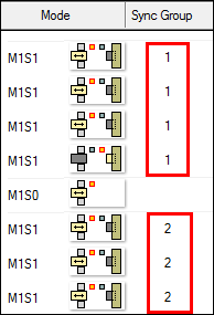
Sync Group — A Synchronization Group contains consecutive processes that are machined using the same Synchronization Mode. For Swiss machining, you can use Synchronization Groups to machine two or more processes simultaneously on different tool posts and/or different spindles.
PartMaker creates Synchronization Groups when you:
- Click
button on the Process Table toolbar; or
- Generate the Process Table using Job Optimizer > Generate Process Table; or
Each Synchronization Group has its own number. For example:
Job details
The Process Table also enables you to view details of the time required to machine the part:
Material File — The material file used for the job.
Main Spindle Time — The total machining time on the main spindle.
Sub-Spindle Time — The total machining time on the sub-spindle.
Total Time — The total time it takes to machine the part.