Alerts are defined within a Live group, within the database, rather than within the model group. These objects can only be viewed and edited when using ICMLive Configuration Manager or InfoWorks ICM Ultimate. We will create two alerts, one for the water level in a node near the outfall and another for the rainfall. For this:
- Ensure the network is opened on the GeoPlan. If using the provided data, please use the Tutorial network- step 5 completed network.
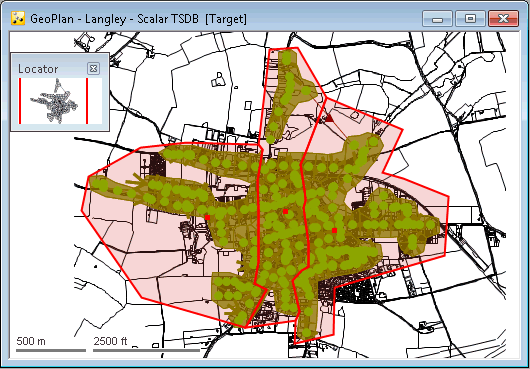
- Select the three rainfall TVD connectors (RG1, RG2 and RG3 polygons) in the GeoPlan:
- Start by clicking a polygon in the GeoPlan. If the Multiple Selection dialog is displayed, ensure the desired TVD connector is selected in the list. It becomes highlighted in the GeoPlan.
- Press the CTRL key and click the second TVD connector. If the Multiple Selection dialog is displayed, ensure the desired TVD connector is selected in the list. It becomes highlighted in the GeoPlan, along with the first TVD connector.
- Repeat the previous step for the third connector.

- Create a selection list called TVD Connectors for these TVD connectors.
- Close the network.
- Within the group, create a Live Group called Live group Tutorial.
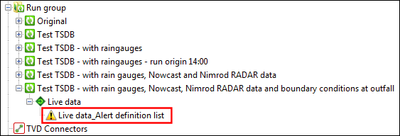
- Within this Live group, create an Alert definition list (ADL) object.
- With the results of the previous simulation open in the GeoPlan (Live Data simulation of the Test TSDB - with rain gauges, Nowcast, Nimrod RADAR data and boundary conditions at outfall run), drag and drop the TVD Connectors selection list onto the GeoPlan.
- Open the Alert definition list, by right clicking on it on the
Explorer window and selecting
Open. Having the ADL open at the same time as the results will allow interaction between the network results and the ADL fields. If a network is not open the user will need to type the information into some of the fields, which is much more likely to result in errors.
Note: If you drag an ADL on top of the results GeoPlan, InfoWorks ICM will attempt to process any alerts, preventing the ADL from being edited.
- We will start by setting up a simple alert which gives information about whether the water level at manhole 45631202 exceeds 3.62 mAD, which would indicate that it is above the invert level of the weir and that flow is being diverted into the storage tanks.
- Add an alert definition with the following properties. For an explanation of the various fields please refer to the
Alert Definition List topic.
Property Value Alert definition ID
45631202_Weir
Priority
1
Category
Overflows
Target type A
Node
Target A
45631202
Target field A
depnod
Comparison operator
>
Target type B
<FIXED VALUE> Target B
3.62
Deadband
0.05
- Let us add a second alert, for the rainfall TVD connectors this time. Create a second alert with the following properties:
Property Value Alert definition ID
Catchment_Rain
Priority
1
Category
Rainfall
Target type A
TVD connector
Target A
<SELECTION LIST>
Target field A
tvd_r
Target selection list A
Select the selection list created earlier (TVD Connectors, see 2)
Comparison operator
>
Target type B
<FIXED VALUE> Target B
10
Transform
Sum over period
Summation period
1h

- The ADL needs to be validated before it can be used in a live system. Validate the ADL before closing it and save it if prompted.
- Close the ADL object.
- To test whether the ADL is working as it should, open the latest simulation in the GeoPlan and drag the ADL on top of the simulation. Note that a new object, an
alert instance list, appears in the tree below the results.

- Open the alert instance list and see what alerts have been generated. An example is given below.

- Close the alert instance list grid.
Alert instances can be shown in alert instance lists, but also on the GeoPlan, as a theme. We are now going to configure a theme for alerts.
