
Changes to orientation, arrangement, and size of parts that leave the geometry unchanged, using mouse and numerical input
Jump to:
What is it?
Moving, rotating, and scaling are operations that have no effect on the geometry of a part. (Technically, scaling changes only the apparent size that is only applied when the mesh is modified, or new meshes or slices are derived from it, such as during repair.)
For example, they don't move mesh vertices (of a single part) against each other, do not remove or add vertices or faces, don't split edges, or do not do anything else that has an impact on the integrity of the complete triangle net of the part. Netfabb maintains this integrity whenever possible and uses internal transformation to replicate any changes from moving, rotating, or scaling.
This is why Netfabb can offer these three operations in one place: Whenever you select any of them, the context view temporarily switches to show the transformation controls.
TopWhat are the key features?
- Regardless which operation you chose first, you can switch between the operations at will.
- You retain view and perspective control of the display. A pop-up dialog would prevent you from clicking anything in the Netfabb window until you closed the dialog regardless whether you performed any action. With the controls placed in the context view, you can zoom, pan, and orbit the camera while you set the transformation up.
- You are free to switch between parts while the controls remain available. This way you can individually align multiple parts to the platform center, for example.
- A scaled part's name receives a numerical value as a suffix. This is the cube root of the scaling factors. The renaming pattern is adjustable in the settings.
Where do I find these controls?
The commands Move and Rotate are located in the main menu, in the Arrange category; the Scale command sits in Modify.
They are also available in the context menu of a part, both in the project tree and the 3D view.
Once called in either way, the context view switches to show the appropriate input fields and buttons. Here you can make use of shortcut buttons that send the selected part to the platform center, or fill the rotation angle field with a value.
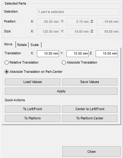
Numerical controls and presets for transforming a part (shown here: moving) are conveniently available in the context view.
Gizmo
A set of manipulation handles, across Autodesk software known as gizmo, appears while the transformation controls are active. The gizmo itself does not have controls for scaling, however.
You can switch the gizmo to become active as soon as a part is merely selected, using .
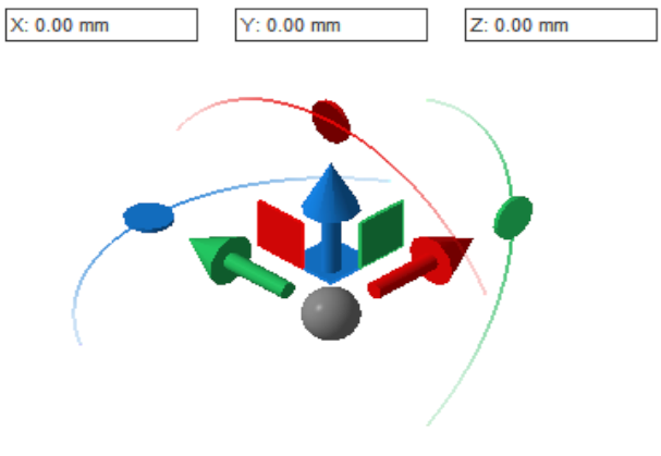
Every element of the gizmo provides interactive control.
- Click and drag an arrow to move a part exclusively along the respective axis.
- Click and drag a square to move a part exclusively along the plane between the adjacent axes.
- Click and drag the gray ball to move a part parallel to the display
- Click and drag a
circle on a crescent to rotate a part about the respective axis.
Tip: If, after clicking, you drag the pointer closer to the center, Netfabb switches to a 5° discretation rather than a continuous angle sweep.
- The numerical fields aren't just for display: After clicking once on any of the listed elements, you can type in the desired values to specify the movement and rotation numerically.
Bounding box controls
You can click and drag or rotate a part by its center marker and the corners of the bounding box bracket:
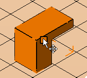
Clicking and dragging the center marker moves the part parallel to the display's depth plane.
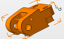
Clicking and dragging the bounding box corners rotates the part around the virtual optical axis of the display.
This is helpful for when you have switched the gizmo to only appear when you actually use any of the functions Move, Rotate and Scale.
Top