
Sets the graphical properties for the selected component definition.
The categories that are displayed in the Symbol Settings dialog box depend on which class you choose to edit. Classes fall into the following categories:
- Equipment, instruments, nozzles, inline components, and most non-engineering components
- Off-page connector and signal connector styles (non-engineering components)
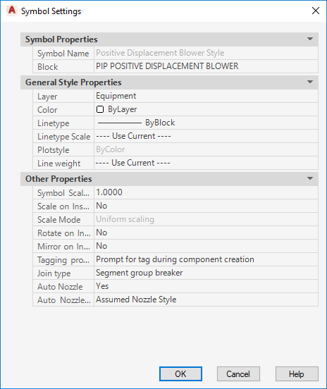
Symbol Properties
Lists the name of the symbol and block used to control the geometry that is displayed for a component after it is inserted into a drawing.
- Symbol Name
-
Defines the name of the symbol. Property is read-only when modifying an existing symbol.
- Block
-
Defines the block that is displayed when the component is used. Click the [...] button to open the Select Block Drawing dialog box, where you choose from a list of available blocks in the Select Block dialog box from the selected drawing.
General Style Properties
Lists the general properties that are assigned to a component when it is inserted into a drawing.
- Layer
-
Defines the layer on which the symbol is applied.
- Color
-
Defines the color applied to the symbol. The style color can be different than the layer color.
- Linetype
-
Defines the linetype applied to the symbol. You can also define the linetype by layer or by block.
- Linetype Scale
-
Defines the linetype scale applied to the symbol.
- Plotstyle
-
Displays the plot styles applied to the symbol.
- Line Weight
-
Defines the lineweight applied to the symbol.
Other Properties
Lists other properties that are assigned to a component when it is inserted into a drawing.
- Symbol Scale Factor
-
Sets the scale for the symbol when it is inserted in a drawing.
Note:The scale specified doesn’t affect the scaling of control valves when it is inserted in a drawing.
- Scale on Insert
-
Sets whether users are prompted to scale the symbol when it is inserted in a drawing.
- Scale mode
-
Sets whether scaling is uniform or XY-independent. This option is available only when Scale on Insert is set to yes.
- Rotate on Insert
-
Sets whether users are prompted to rotate the symbol when it is inserted in a drawing.
- Mirror on Insert
-
Sets whether users are prompted to mirror the symbol when it is inserted in a drawing.
- Tagging Prompt
-
Sets whether users are prompted to tag the symbol when it is inserted in a drawing. This field is displayed for all style types except off-page connectors, and lines and instrument signal connectors.
- Join Type
-
Defines the join type applied to a symbol. This field is displayed for all style types except lines, off-page connectors, and lines and instrument signal connectors. One of the following join types can be assigned to a symbol:
- Endline. Does not insert into lines. Connects at ends of lines.
- Inline. Inserts into a line and behaves as part of the line.
- Segment Breaker. Inserts into a line and breaks the line into two segments in the same group. Retains the line group and line number for both line segments.
- Segment Group Breaker. Inserts into lines and breaks line into two segments and two line groups.
- No Join. Does not connect with lines.
- Auto Nozzle
-
Sets whether a component has nozzles attached automatically when a pipe line is connected to a component. This field is displayed for all style types except lines, off-page connectors, and lines and instrument signal connectors.
- Auto Nozzle Style
-
Defines the nozzle style. This field is displayed for all style types except lines, off-page connectors, and lines and instrument signal connectors.