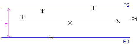
When you probe a plane using more than three probed points, PowerInspect creates a best fit plane (P1) that minimizes the deviations of all the points. It then runs two parallel planes (P2 and P3) through the furthest points in the positive and negative directions, and the distance between P2 and P3 (F) is reported as the Flatness of the plane. If this distance is greater than the Maximum value, the flatness is reported as being out of tolerance.
- Release Notes
- Subscription Benefits
- Getting Started
- Help
- PowerInspect Basics
- Setting up the Machine
- Calibrating the Probe
- Working with CAD
- Defining Alignments and Datums
- Creating the Sequence
- About the inspection sequence
- To create and edit an inspection sequence
- To exclude anomalies from the fitting calculation of an item
- Inspection sequence item status reference
- Probe path verification icons reference
- To use the tolerance database
- To work with items in the CAD View
- Geometric Inspection
- To work with geometric groups and geometric items
- To create geometric features from the CAD model
- To specify tolerances for the Wireframe Checker
- Planes
- To create a Probed Plane item
- To create a Probed Parallel Plane item
- To create a Plane: Point & Vector item
- To create a Bisector Plane item
- To create a Plane: Line & Vector item
- To create a Plane: Line & Point item
- To create an Offset Plane item
- To create a Plane: Parallel & Distance item
- To create a Plane: Parallel Via Point item
- Lines
- Points
- Circles
- Slots
- Rectangles
- Polygons
- Ellipses
- 3D Features
- Point Clouds
- About probing features manually
- To measure geometric features manually
- To control the information displayed when probing features manually
- To measure geometric features with a laser scanner
- Free-Form Inspection
- Probe Paths
- GD&T
- Point Clouds
- Digitised Curves
- Simple Measures
- To create a CAD View State item
- To create a Comment item
- To create a Change Probe item
- To create a Custom Stop Continue item
- To create a Custom Action item
- Simulating and Collision-checking
- Measuring
- Analysing Results
- Corrective Action
- Reporting
- Collaborating with Others
- Digital Read-Out Help
- Video Library
- Autodesk Installation