
This example shows how view toolpaths by Z height, and how to use the Z Heights dialog. It uses the flats.dgk model in the Examples folder.
- Define a Block around the model.
- Create a
Model Area Clearance strategy, and:
- Select Style as Offset all.
- Enter a Stepover value of 5.0.
- Create an end mill tool with a Diameter of 5.0.
- Click Calculate to create the toolpath.
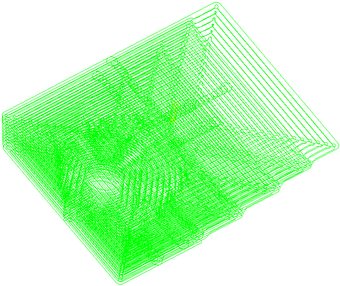
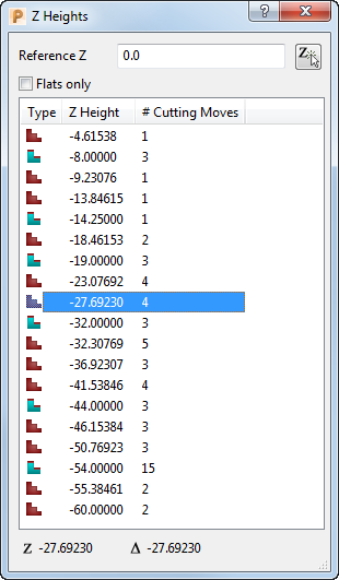
- Click Toolpath tab > Draw panel > View by Z Height to display the Z Heights dialog. The Z heights available in the toolpath are listed in the Z Height list.
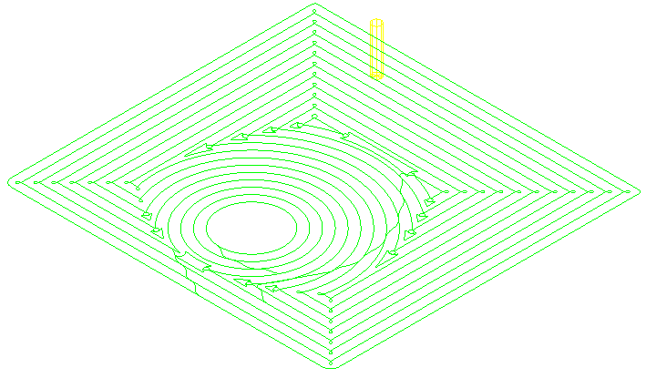
- Click through the list to view the toolpath segment at a particular Z height.
You can also:
- Enter a Reference Z to view the toolpath segment nearest to the entered value.
- Click
 to pick a Z height from the model to use as the reference Z.
- Select Flats only to view the toolpaths segments associated with only flat regions of the model.
Note: If you select a segment and click Toolpath tab > Draw panel > View by Z Height, the graphics window displays the selected Z height.