
This option is helpful when viewing any Z height dependent toolpaths. For example, area clearance, constant Z, and flat-finishing strategies. The Z height viewing options are not available for other types of toolpaths.
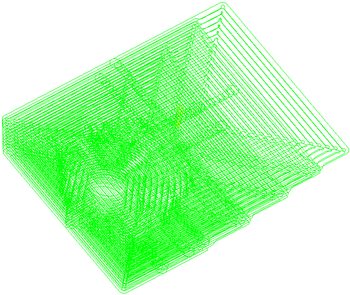
Viewing a toolpath without isolating a Z height level:
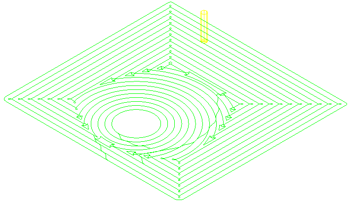
Viewing a toolpath at an isolated Z height level:
To view an individual Z height slice of a toolpath, with the toolpath activated, click Toolpath tab > Draw panel > View by Z Height to display the Z Heights dialog, click through the Z Height list to examine the toolpath segments at the particular Z height.
The Z Heights dialog contains the following:
- Reference Z — Enter a reference Z value to view the toolpath segment nearest to the entered value.
 Pick a Z height from the model using the mouse — Click to select and set a reference Z from a particular feature of the model.
- Flats only — Select to view the toolpath associated with flat regions of the model.
- Z — Displays the current Z height.
 — Displays the difference between the current Z height and the reference Z.
To simulate tool movements at a particular Z height, right-click on the toolpath segment that you want to simulate, and select Toolpath > Simulate from Nearest Point.