
Use the Single Blade Finishing strategy to create toolpaths to machine single-blade aerofoils.
To display the Single Blade Finishing strategy page, select Single Blade Finishing from the Blisk page of the Strategy Selector dialog. The page contains the following options:
Curve definition specifies the curves bounding the area you want to machine and adds the machining properties to those curves. The pattern must contain two or more curve segments.
 Create pattern — Click to create a new empty pattern. You can then collect wireframe curves and add them to the empty pattern using the Collect curves
  button.
 Selected pattern — Select a pattern from the list. If no pattern is displayed, or
  is selected, then no pattern is selected. The list contains a list of all available patterns.
 Curve Editor— Click to display the Curve Editor for the selected pattern. If no pattern is selected, PowerMill creates a new pattern. Use the Curve Editor to create planar sections that are used to define single blade finishing toolpaths.
 Select picked pattern — Click to select a pattern by picking in the graphics window, rather than by name in the
Select pattern list.
Select picked pattern — Click to select a pattern by picking in the graphics window, rather than by name in the
Select pattern list.
Clicking displays the Pick Entity tab. Select a pattern in the graphics window to close the Pick Entity tab and display the pattern in the Selected Pattern field.
Collect curves — Click to copy the selected curves into the pattern. Use this option if you want to collect wireframe curves.
This provides a fast, powerful means of extracting curve geometry from a surface model and copying it into the active pattern/boundary. You can insert:
- Individual surface boundary curves.
- Boundary curves around a selection of surfaces.
- Model wireframe geometry.
- Existing pattern or boundary segments.
- Click to display the Collect Curves tab. For more information, see the collecting curves example.
 Select curves — Displays the Single Blade Curvetab. This enables you to make changes or setup the curve definition.
Status — Displays information about the pattern you have selected:
- No pattern — No pattern is selected.
- Not defined — The pattern contains more than 3 segments.
- Valid — The pattern contains 2 closed curves (and optionally 1 open curve).
- Invalid — The pattern does not contain any segments or does not contain 2 closed segments.
Minimise Axis Movement — Select to follow the surface normal less accurately on curved parts of the model. This creates a smoother and faster machine motion. The cutting tool rolls around the curved parts of the blade, for example, the leading and trailing edges. Select this option for roughing or semi-finishing toolpaths where cycle time is more important than surface finish.
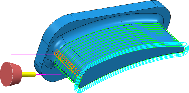
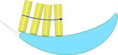
Spiral — Select to enable the toolpath to spiral around the aerofoil. Spiral toolpaths are typically more efficient than non-spiral toolpaths as they do not contain lead-in or lead-out moves. Spiral toolpaths also avoid shock-loading the cutting tool as it leads into and out of stock. This creates a consistent surface finish and improves the cutting life of the tool.
Toolpath with Spiral selected:
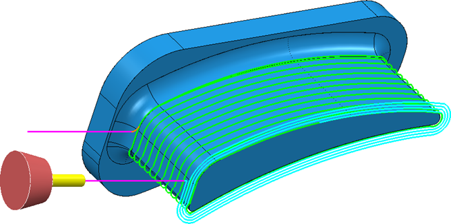
Toolpath with Spiral deselected:
Cut direction — Select a milling style:
- Climb — Select to create toolpaths using only climb milling, where possible. The tool is on the left of the machined edge when viewed in the direction of tool travel.
- Conventional — Select to create toolpaths using only conventional or upcut milling, where possible. The tool is on the right of the machined edge when viewed in the direction of tool travel.
Tolerance — Options to specify how accurately the toolpath follows the contours of the model.
- Surface joining tolerance — Enter a tolerance value to determine if toolpaths can cross gaps between surfaces. For example, to create a continuous toolpath across a gap, enter a large Surface joining tolerance. To split toolpath segments between surfaces, enter a small Surface joining tolerance.
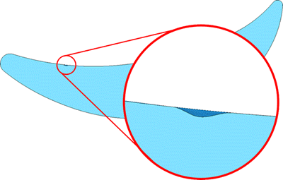
- Model Defect Removal Tolerance — Use this option to smooth toolpaths and ignore small defects in your CAD model. Enter the maximum defect thickness that is ignored by the toolpath. Model Defect Removal Tolerance improves the machining quality, as the tool does not dwell on defects below a specified size.
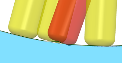
For example, this aerofoil contains a defect that is 0.25 mm deep:
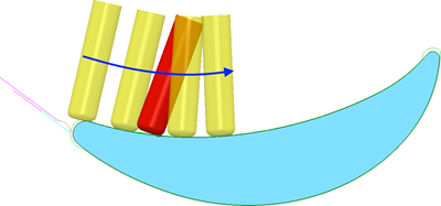
If Model defect tolerance is set to 0.01 mm (default) PowerMill generates a toolpaths where the tool tip rolls into the defect. The tool axis wobbles, which results in an unacceptable machine motion:
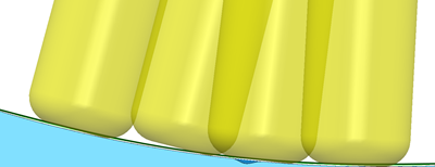
If you enter a Model defect tolerance that is greater than the defect size (for example, 0.5 mm), PowerMill ignores the defect and produces a smooth toolpath:
Tolerance — Enter a value to determine how accurately the toolpath follows the contours of the model.
Thickness — Enter the amount of material to be left on the part.
 Component thickness — Click to display the
Component thickness
dialog, which enables you to specify the thicknesses of the different surfaces.
Component thickness — Click to display the
Component thickness
dialog, which enables you to specify the thicknesses of the different surfaces.
Stepover — Enter the distance between successive machining passes.