
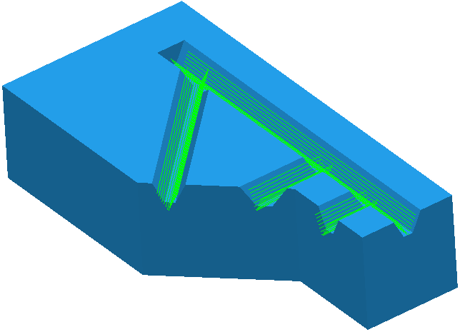
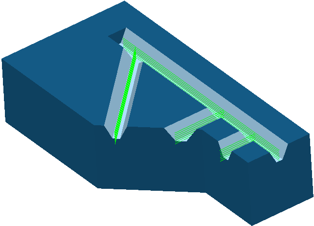
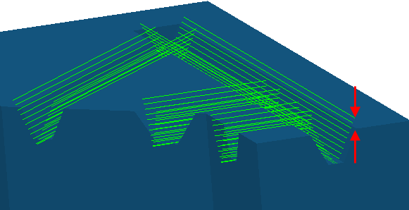
Use the Rib machining page to create a toolpath by machining a channel (or groove) in a part.
Pattern — This defines the approximate centreline of the channel.
 Selected pattern — Select a pattern from the list. If no pattern is displayed, or
 is selected, then no pattern is selected. The list contains a list of all available patterns.
 Rib pattern — Click to display the
Rib Pattern Editor tab, which enables you to sketch the approximate centreline of the channel.
Rib pattern — Click to display the
Rib Pattern Editor tab, which enables you to sketch the approximate centreline of the channel.
 Create pattern — Click to create a new empty pattern.
 Select picked pattern — Click to select a pattern by picking in the graphics window, rather than by name in the
Select pattern list.
Select picked pattern — Click to select a pattern by picking in the graphics window, rather than by name in the
Select pattern list.
Surfaces — This defines the surfaces forming the walls and base of the channel.
 Create a set
— Click to create a new set, which is the reference set.
Create a set
— Click to create a new set, which is the reference set.
- Selected set — Select a set from the list. Sets contain the surfaces that form the walls and base of the channel.
 Rib surface — Click to display the
Rib Surface Editor tab, which enables automatic selection of the wall and base surfaces of the channel.
Rib surface — Click to display the
Rib Surface Editor tab, which enables automatic selection of the wall and base surfaces of the channel.
Style — Select whether you want to machine down both walls of the channel or down the centreline.
Selecting a Style of Rib walls creates a toolpath that machines down one side of the channel and then the other side. Use this option when the tool is smaller than the channel.
Selecting a Style of Rib centre creates a toolpath that machines down the centreline of the channel. Use this option when the tool, frequently a form tool, is the size and shape of the channel.
Selecting a style of Centre and walls creates a toolpath that machines down the centreline of the channel and then machines down each side of the channel.
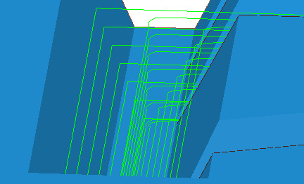
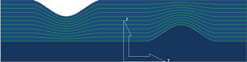
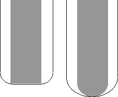
Clearance — When the top surface is not fully machined, enter the height above the top of the top of the channel where the machining starts.
For example a Clearance of 0 gives:
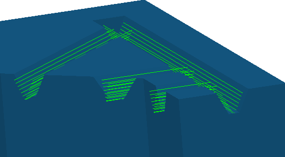
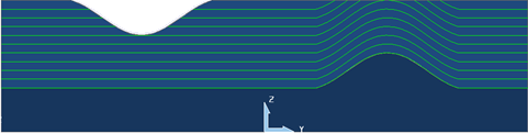
A Clearance of 10 gives:
Offset — Select how to offset from the base surface to the top of the channel.
- Merge — Select to offset the base profile and migrate the offset so that at the end it is offsetting the top profile. This minimises the number of air moves.
- Offset up — Select to offset the base profile. This option gives a consistent depth of cut and minimises the number of downhill moves. This is important when your tool cannot make cutting moves where Z decreases.
You can eliminate the downhill moves by selecting a Cut direction of Uphill.
- Floor only — Select to create a toolpath along the base of the channel.

- Constant Z
— Select to create toolpaths with a constant Z height.
Tolerance — Enter a value to determine how accurately the toolpath follows the contours of the model.
Cut direction — Select the milling technology:
- Climb — Select to create toolpaths using only climb milling, where possible. The tool is on the left of the machined edge when viewed in the direction of tool travel. Use this option when you have a
Style
of
Rib walls. When you have a
Style
of
Rib centre one side of the tool is climb milling and the other is conventional milling.
- Conventional — Select to create toolpaths using only conventional or upcut milling, where possible. The tool is on the right of the machined edge when viewed in the direction of tool travel. Use this option when you have a
Style
of
Rib walls.
- Any — Select to create toolpaths using both conventional and climb milling. This minimises the tool lifts and tool travel.
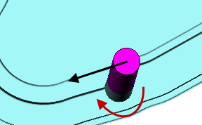
- Pattern — Select to create a toolpath that follows the direction of the pattern. This option uses both climb and conventional milling. When you select a
Style of
Rib walls, one wall is machined using climb milling and the other using conventional milling to ensure the tool follows the direction of the pattern. With open channels, use this option to start machining from the open end of the channel to avoid plunge moves. To see the direction of the pattern, click Rib Pattern Editor tab > Draw panel > Instrumentation to instrument it.
To display the Rib Pattern Editor tab, click
.
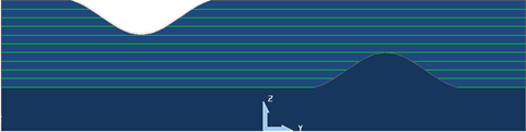
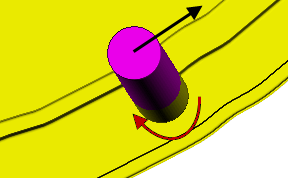
- Uphill — Select to create a toolpath that avoids cutting moves where Z decreases. This option uses both climb and conventional milling. When you select a
Style of
Rib walls, one wall is machined using climb milling and the other using conventional milling to ensure the tool never makes a decreasing Z move.
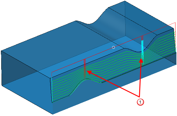
 additional toolpath lifts added to avoid cutting moves where Z decreases
Machine with tool taper angle — When selected, the tool machines the channel using its taper angle instead of the draft angle of the channel. This is useful when the channels are not modelled accurately, do not need to be machined accurately, or you have a form tool that matches the profile of the channel.
Angular tolerance — Enter the maximum deviation from the draft angle of the channel to the tool taper angle. When this angle is exceeded, PowerMill leaves a portion of the channel unmachined.
Thickness — Enter the amount of material to be left on the part. Click the
Thickness
 button to separate the
Thickness
box in to
Radial thickness
button to separate the
Thickness
box in to
Radial thickness
 Axial thickness
 . Use these to specify separate
Radial and
Axial thickness as independent values. Separate
Radial and
Axial thickness values are useful for orthogonal parts. You can use independent thickness on sloping walled parts, although it is more difficult to predict the results.
. Use these to specify separate
Radial and
Axial thickness as independent values. Separate
Radial and
Axial thickness values are useful for orthogonal parts. You can use independent thickness on sloping walled parts, although it is more difficult to predict the results.
Radial thickness — Enter the radial offset to the tool. When 2.5-axis or 3-axis machining, a positive value leaves material on vertical walls.
Axial thickness — Enter the offset to the tool, in the tool axis direction only. When 2.5-axis or 3-axis machining, a positive value leaves material on horizontal faces.

 Component thickness — Click to display the
Component thickness
dialog, which enables you to specify the thicknesses of the different surfaces.
Component thickness — Click to display the
Component thickness
dialog, which enables you to specify the thicknesses of the different surfaces.
Max stepdown — Enter the maximum distance between successive passes.
 Copy stepdown from tool
— Click to load the axial depth of cut from the active
tool's cutting data. The axial depth of cut is measured along the tool axis.
Copy stepdown from tool
— Click to load the axial depth of cut from the active
tool's cutting data. The axial depth of cut is measured along the tool axis.
 .
.
Order — Select the machining order of the selected channels:
- Pattern — Select to machine the channels in the same order as you created the pattern.
- Shortest — Select to create the shortest toolpath. This minimises the air moves.