You can use this option only if a segment was inserted previously. The Side View option selected in the Shaft Generator Configuration dialog box, determines how the sectional view will be drawn or updated.

- In the Shaft Generator dialog box, select the Section icon.
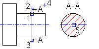
- Specify the position of the cross-section (1) and the starting point of the section line (2).
- Specify the endpoint of the section line (3). Press Enter to have the endpoint be the symmetrical point of the starting point.
- In the Hatch Parameters dialog box, specify a hatch pattern, and then choose OK.
- Press Enter to assign the letter to the arrows of the cross-section line (letters in alphabetical order are provided as default for multiple sectional views of the shaft).
- Determine the side of the cutting plane (4).
- Specify the insertion point to determine the position of the sectional view (5).
Note:
- Two types of sections are available in the Configuration dialog box. The first type is a true section considering further sections in the background. The second type is a cross section with fully displaying the background.
- The cross section can be positioned anywhere in the drawing. However, no checking is performed to see whether the cross section overwrites a portion of the shaft. The cross section is labeled with the specified designated letter.
- If the Always Update option in the Configuration dialog box is not selected, the side views and cross sections are not updated with the new values during editing of shaft sections. You can, however, select a cross section or a side view with the Edit command. Start the Edit command. In the dialog box that displays, press Enter to confirm all requests. The updated views will be displayed. During the editing process, the starting and endpoints, cross-section letters, and view direction remain unchanged.