
Learn how you can work with user sections in your 3D model.
All sections, including user sections, are stored in databases. The table structure for user sections differs from the structure of standard sections. Standard section tables contain parametric values whereas user sections include only the corner points of the cross section geometry.
User sections are not manually entered in database tables; they are drawn and transferred by means of the Advance User Section tool that identifies the profile cross section and enters the geometry into the databases.
Define User Sections
Create section components
The section components are drawn with AutoCAD elements. Next, you need to create two texts with the name of the section (e.g. IPE 200) and the name of the section class (e.g. IPE). For each user section component you must set a corresponding layer. You can do this by using the Change current layer flyout.
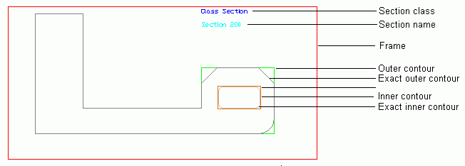
The user section components
-
The definition frame must include the whole section contour with all its information and is required to create the section.
-
The outer contour defines the standard representation of the section in the model and should not include too many details to avoid a complex representation in the model.
-
The exact outer contour
The exact outer contour defines the exact outline of the section that is used for clash checking, drawings and weight calculation.
The outer contours must be created using a closed polyline, a circle, or a rectangle.
-
Section inner exact and simple contour
Closed polylines, circles and rectangle are allowed as elements. The inner contour is necessary, for example, to create hollow sections.
The exact inner contour defines the exact outline of the hollow section that is used for clash checking, drawings and weight calculation.
-
Section name
The text for the section name.
-
Section class
The text for the section class name that will appear on the Section&Material tab in the Advance properties dialog box.
Add system coordinates
The coordinate systems that are displayed when using UCS at object.
The coordinate system is inserted when selecting one face from the outer contour; the Z-axis is placed along that face.
Add a reference axis
The reference axis position is used to move the section around the reference line on the Position tab in the properties dialog box.
The reference axes are added on the outer contour. The tools for placing reference axes are grouped on the User sections panel, Add reference axis flyout.
Section definition and identification of the drawn elements
The information is proofed and created in the database.
User section tools
The tools for creating user sections are grouped on the Extended Modeling tab, User sections panel, on the flyouts.