
Use the Constant Z finishing page to specify settings for creating a toolpath that slices the model at specific heights (or levels).
Order by — Select whether machining takes place by Region or by Level.
- Region — When selected, one region (such as a pocket or boss) is completely machined before going on to the next. So, pockets are machined in preference to levels.
- Level —When selected, one level is completely machined before going down to the next. So, levels are machined in preference to pockets.
Additional stock — Use this option to help with ordering when machining between two steep walls so PartMaker produces a safe order with the level of stock specified here. Providing the passes are within the distance specified, an alternating toolpath is created, machining at one machining-level height on one wall, and then at the same height on the neighboring wall before descending to the next machining-level height.
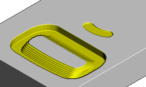
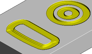
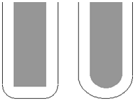
Spiral — Select this option to create a spiral path between two consecutive closed contours.
This minimizes the number of lifts of the tool and maximizes cutting time while maintaining more constant load conditions and deflections on the tool.
- With Spiral deselected:
- With Spiral selected:
Undercut — Select this option to produce a toolpath where the cutter can touch the part, so you can machine areas with undercuts. Undercut works with Slot Mill tools only.
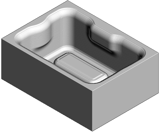
If you start with this model:

- With Undercut selected:
- With Undercut deselected:
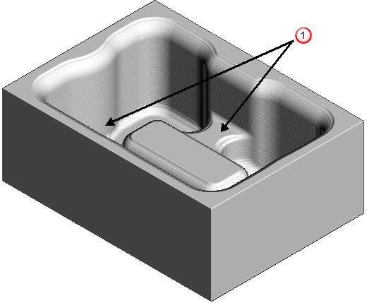
 — Areas not fully machined.
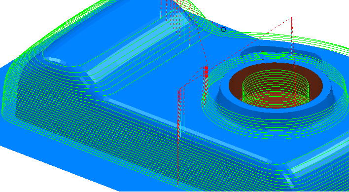
Machine down to flats — Select this option to add a constant Z slice on flat surfaces at the bottom of steep features.
- With Machine down to flats selected:
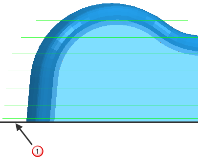 — Flat surface
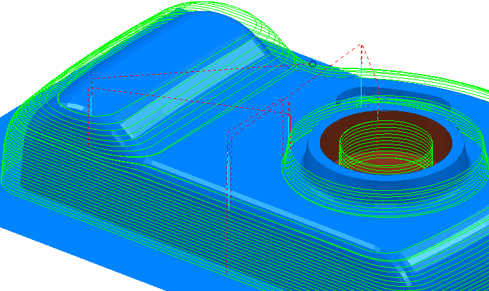
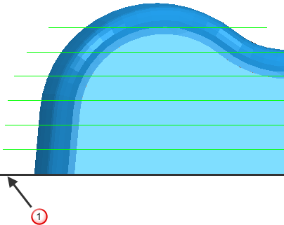
 - With Machine down to flats deselected:
Flat tolerance — Enter the Z range that determines whether a surface is flat.
Tolerance — Enter a value to determine how accurately the toolpath follows the contours of the model.
Cut direction — Select the milling technology.
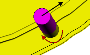
- Climb — Select to create toolpaths using only climb milling, where possible. The tool is on the left of the machined edge when viewed in the direction of tool travel.
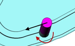
- Conventional — Select to create toolpaths using only conventional or upcut milling, where possible. The tool is on the right of the machined edge when viewed in the direction of tool travel.
- Any — Select to create toolpaths using both conventional and climb milling, as appropriate. This minimizes the tool lifts and tool travel.
Thickness — Enter the amount of material to be left on the stock within tolerance. Thickness is applied as an offset to the tool in all directions:
Stepdown
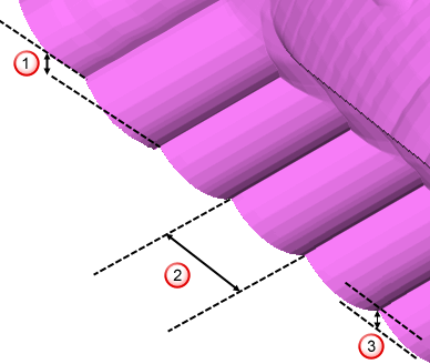
Minimum stepdown — Enter the constant stepdown value between successive machined levels.
Calculate using cusp — Select this option to determine the stepdown by the Cusp height, with a maximum stepdown determined by the Maximum stepdown value. When deselected, the stepdown between successive Z heights has a constant value equal to the Minimum Stepdown value.
Maximum stepdown — Enter the maximum allowable stepdown when calculating the stepdown using the cusp height. This prevents excessive stepdown on vertical walls.
Cusp height — Use this setting to specify the stepdown so that the height of the material left between Z Heights does not exceed the Cusp Height. However, if the calculated value is smaller than the Minimum Stepdown, it is set to Minimum Stepdown.
Stepdown
 Stepover
 Cusp height