
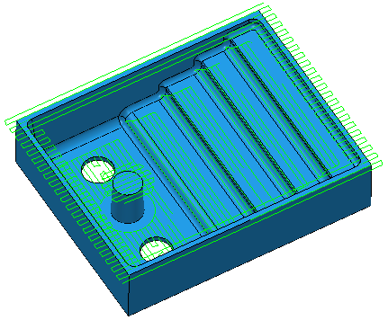
Use the Raster flat finishing page to specify settings for creating a raster toolpath on the flat areas of a model.
Flat tolerance — Enter a tolerance to find areas that are almost flat (that is, flat within the tolerance specified here).
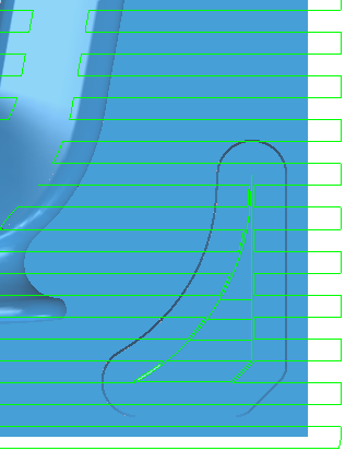
Allow tool outside flat — Select this option to allow the tool to go outside the flat area. This alleviates the problem of running the tool along a sharp edge.
Select Allow tool outside flat:
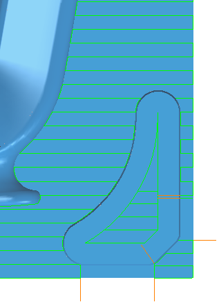
Deselect Allow tool outside flat
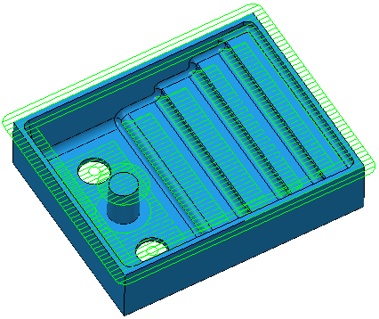
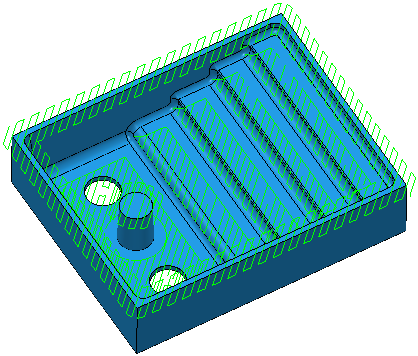
Add approaches from outside — Select to specify that PartMaker allows level moves to approach the model from outside the block.
Approach outside allowance — Enter the approach distance. This is the maximum approach distance from the flat.
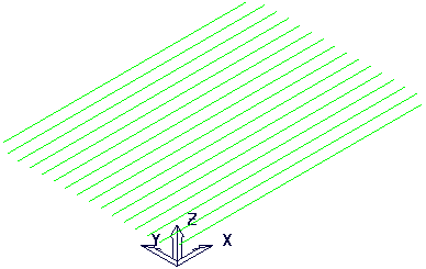
Fixed direction — Select to specify the angle of passes in the Angle field. When deselected, PartMaker automatically calculates the most appropriate angle.
Select Fixed direction
Enter an Angle of 0:
Select Fixed direction
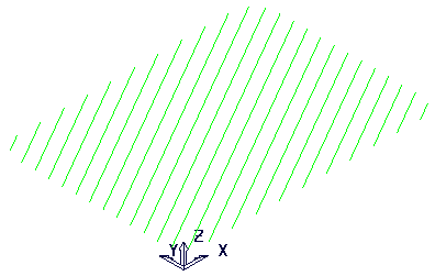
Enter an Angle of 45:
Deselect Fixed direction:
Angle —Enter the angle of the passes relative to the X axis.
- With an Angle of 0
 :
:
- With an Angle of 30:
Tolerance — Enter a value to determine how accurately the toolpath follows the contours of the model.
Cut direction — Select the milling technology.
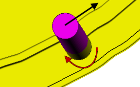
- Climb — Select to create toolpaths using only climb milling, where possible. The tool is on the left of the machined edge when viewed in the direction of tool travel.
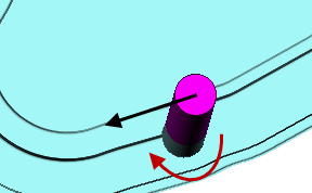
- Conventional — Select to create toolpaths using only conventional or upcut milling, where possible. The tool is on the right of the machined edge when viewed in the direction of tool travel.
- Any — Select to create toolpaths using both conventional and climb milling, as appropriate. This minimizes the tool lifts and tool travel.
Thickness — Enter the amount of material to be left on the stock within tolerance. Thickness is applied as an offset to the tool in all directions:
Stepover —Enter the distance between successive machining passes.