
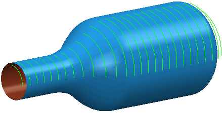
Use the Rotary finishing page to create a toolpath by rotating the job around the Z axis, with linear motion provided by the X and Y axis pair.
The following settings are available:
Z limits —Enter the absolute limits of the finishing path along the Z axis in the Start and End fields.
- Using the limits of the block:
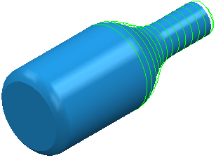
- Using Z limits Start of 50 and Z limits End of 102:
Pattern
Style — Select the milling technique (Circular, Linear, or Spiral).
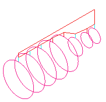
- Circular — Select this option so the job rotates with the tool at a fixed position, effectively machining a circle. The tool then steps over the required amount and machines the next circle.
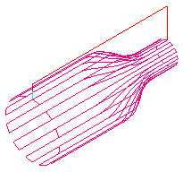
- Linear — Select this option to so the tool traverses along the Z axis in straight lines, with the rotary axis only used at the end of each pass to reposition the job.
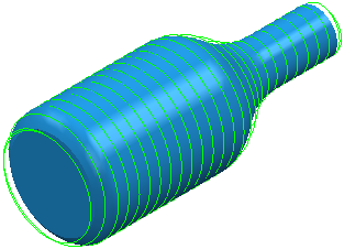
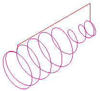
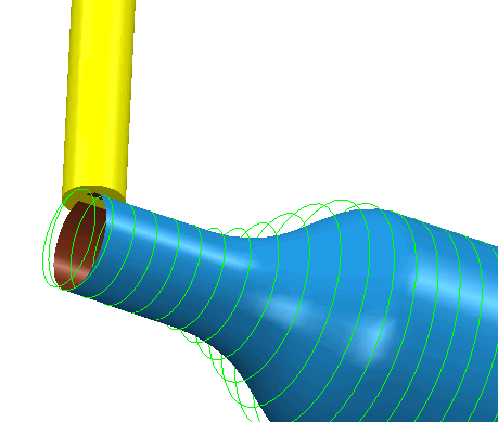
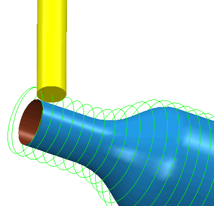
- Spiral — A continuous spiral is cut along the length of the job. To ensure a clean finish, a full circle is cut at the two ends.
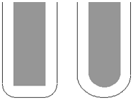
Y-offset — Enter a non-zero distance to avoid cutting on the center of the tool.
- With a Y offset of 0 cuts using the center of the tool:
- With a Y offset of 10 cuts using the position on the tool located 10mm from its center:
Angular limits — Enter the angular positions at which machining starts and ends. Start defines the angular position at which machining is to start. End defines the end angle. The angular limits are measured in a counterclockwise direction when viewed along the positive Z axis. The area machined is between the start and end angles.
- With a Start of 0
 and an End of 360.
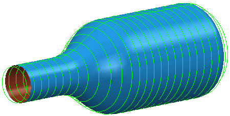
- With a Start of 0 and an End of 90.
Tolerance — Enter a tolerance value to determine how accurately the toolpath follows the contours defined by the model.
Cut direction — Select the milling technology.
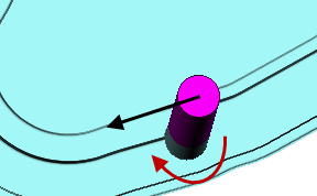
- Climb — Select to create toolpaths using only climb milling, where possible. The tool is on the left of the machined edge when viewed in the direction of tool travel.
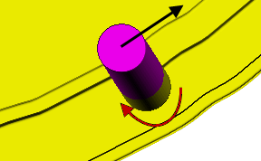
- Conventional — Select to create toolpaths using only conventional or upcut milling, where possible. The tool is on the right of the machined edge when viewed in the direction of tool travel.
- Any — Select to create toolpaths using both conventional and climb milling, as appropriate. This minimizes the tool lifts and tool travel.
Thickness — Enter the amount of material to be left on the stock within tolerance. Thickness is applied as an offset to the tool in all directions:
Stepover —Enter the distance between successive machining passes.