Use the Wireframe swarf finishing page to create a swarf toolpath from two profile curves. PartMaker creates a toolpath cutting with the side of the tool as the tool follows the two curves. As with Swarf machining you must be able to create a developable surface from the two curves. For more information see Swarf machining.
To specify the profile curves you want to use as the top and bottom swarfing curves, double-click on a profile in the CAM Face window to display the Curve Properties dialog.
Drive curve
Use these settings to determine which surface, or set of surfaces, are used to create the cutting moves.
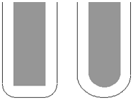
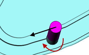
Wireframe side — Select the position of the tool for the top swarfing curve.
- Left — Select for the tool axis stays to the left of the curve by a distance equal to the tool radius (see
 ).
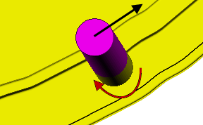
). - Right — Select for the tool axis to stay to the right of the curve by a distance equal to the tool radius (see
 ).
).
Angular rulings tolerance — Enter the angular tolerance used when generating ruling between two wireframe curves. This creates the ruling by matching the top and bottom normals within the angular tolerance. This is similar to the creation of developable surface from two rail curves.
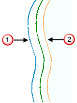
Radial offset — Enter the gap between the tool and the surface.
— Radial offset: 0
— Radial offset: 5
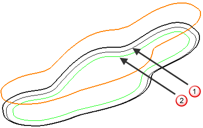
Minimum fanning distance — As the toolpath moves from one surface to another there can be a change in the ruling direction. Because the tool aligns itself with the ruling direction, you have to specify the distance over which the tool can change from one ruling direction to the next. The fanning distance is measured as the smallest movement on either surface edge (or the distance the closest part of the tool is to the opposite part of the surface before fanning starts). PartMaker automatically increases the Minimum fanning distance if the value specified causes gouging.
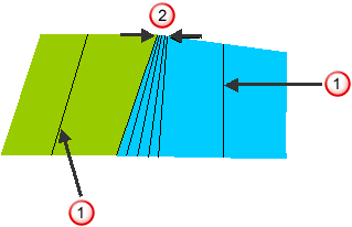
— Ruling direction.
— Fanning distance.
Fan at end on planes — Select so fanning occurs only in the end region of a plane. When deselected, fanning occurs everywhere.
Tolerance — Enter a value to determine how accurately the toolpath follows the contours of the model.
Cut direction — Select the milling technology.
- Climb — Select to create toolpaths using only climb milling, where possible. The tool is on the left of the machined edge when viewed in the direction of tool travel.
- Conventional — Select to create toolpaths using only conventional or upcut milling, where possible. The tool is on the right of the machined edge when viewed in the direction of tool travel.
- Any — Select to create toolpaths using both conventional and climb milling, as appropriate. This minimizes the tool lifts and tool travel.
Thickness — Enter the amount of material to be left on the stock within tolerance. Thickness is applied as an offset to the tool in all directions: