
Functions and options explained
Jump to:
- Buttons in the context view
- Common tabs
- Polygon cut
- Polygon edge configuration
- Circle cut
- Rectangle cut
Buttons in the context view
| Button | Function | Note |
|---|---|---|
 Create polyline Create polyline
|
Create the cutting stencil as arbitrary polygonal line by successively adding more points. | |
 Create circle Create circle
|
Create the stencil as a circle with a centerpoint and a radius. | |
 Create rectangle Create rectangle
|
Create the stencil as a rectangle with a centerpoint, a width, a height, and a rotational angle. | |
 Edit edge Edit edge
|
Opens the dialog to define matching features on all polygon edges for joining parts. | Only available for arbitrary polygons |
 Select and position parts Select and position parts
|
Temporarily fixes the stencil and lets you move the part against the stencil | |
 Reset perspective to cutting direction Reset perspective to cutting direction
|
Changes perspective to look perpendicularly onto the cutting stencil | |
 Reset polygon Reset polygon
|
Clears all stencils |
Common tabs
These tabs are available for all modes, for polyline, circle, and rectangle alike.
Borders
- Enable Add tolerance spacing to add some offset to the cutting line which can help reassembling the part later while still maintaining the correct measurements.
- Choose between Inside, Outside, or Both sides for the offset location.
- Enter a value for the tolerance spacing between the offset line and the original line.
- Enable the Create round corners check box to round eligible corners of the cutting. Using the slider you can quickly set up a corner radius between 0 and 10 mm. Using the input field you can specify radii beyond 10 mm. A corner is eligible if the resulting center point of the specified radius doesn't come to lie too far away from the associated corner point, otherwise no rounding is applied.
Information
- Lists the count of points used to form the current shape as well as the volume of the stencil regardless of the actual intersection of part and stencil
Polygon cut
Load/Save
- Stores custom polygon cut definitions in a dropdown and enables sharing these definitions as files.
Polygon edge configuration
- Select the Count radio button to determine how many edge features are created on each edge or select the Distance radio button to determine the spacing between the edge features.
- Select a Pin type from the drop-down menu. Available options are: Dove tailed, Jagged, Puzzle
- Edit the dimensions of the selected pin type as required.
Mouse controls for edge feature configuration
- Drag a feature's edge points to adjust shape and size.
- Drag the feature's base point to move the feature along the edge
- Alt+Drag a feature's base point to
move ALL features along the edge.
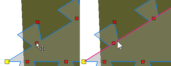
Point exactly at the base point first, then hold Alt, then drag. (left) If the edge becomes highlighted, Alt+Click straightens the edge instead. (right)
- Right-click a feature's base point to choose from a context menu. Here you can remove the individual feature ("pin") and also distribute the features evenly along the edge.
Rectangle cut
Properties
- Controls to specify the rectangle's width and height
Cutting options
- Algorithm: The standard algorithm is faster but doesn't maintain colors or textures. The algorithm that does maintain this is only available for arbitrary polygon cuts without edge feature definitions.
- Transparency: Adjusts the transparency of the gray fill area in polygon cut definitions
- Resolution factor: Affects the triangle density of surfaces created by cutting
- Cutting depth: Creates a blind hole with a given depth instead of cutting all the way through the part
- Only selected parts: When enabled, only selected parts are cut even when the plane or stencil goes through other parts as well.
- Stitch parts: When enabled, open triangle edges are connected.
- Remove original parts: Removes the original parts after the cutting operation.
- Close cutting area: When enabled, holes that emerge as a result of the cut are closed automatically with a flat surface across the cut.
- Create group: When enabled, cut results are grouped.
- Keep colors, Keep textures: Attempts to maintain color values and texture coordinates on cut-offs