
Limit specifies the area that you want to machine. This page contains the following:
Boundary — Use these option to limit the machining area.
 Create boundary — Select an option to create a new boundary. This works in exactly the same way as the
Create Boundary
option on the
Boundary tab or from the
Boundaries context menu.
Create boundary — Select an option to create a new boundary. This works in exactly the same way as the
Create Boundary
option on the
Boundary tab or from the
Boundaries context menu.
 Selected boundary — Displays the boundary used to limit the toolpath. Select a boundary to make it the active boundary. If you don't want to use a boundary to calculate the toolpath, select
<None> from the list.
Selected boundary — Displays the boundary used to limit the toolpath. Select a boundary to make it the active boundary. If you don't want to use a boundary to calculate the toolpath, select
<None> from the list.
 Curve Editor — Click to display the
Curve Editor tab, which enables you to create and edit boundaries. The assumption is that you extract curves from the model, by extracting curves at surface boundaries, before modifying the curve to create the exact boundary you need.
Curve Editor — Click to display the
Curve Editor tab, which enables you to create and edit boundaries. The assumption is that you extract curves from the model, by extracting curves at surface boundaries, before modifying the curve to create the exact boundary you need.
 Edit boundary — Click to edit the selected boundary. This displays the
Boundary dialog. This is the same dialog displayed when you create or edit a boundary.
Edit boundary — Click to edit the selected boundary. This displays the
Boundary dialog. This is the same dialog displayed when you create or edit a boundary.
Boundary Limit — This determines which part of the tool can touch the boundary.
 Tool Centre — When selected, the centre of the tool cannot go outside the boundary.
 Tool Periphery — When selected, the whole tool is contained within the boundary. The boundary is offset inwards by the tool radius.
For more information on how these limits work, see Limiting a toolpath by a boundary. This option is available only for area clearance toolpaths.
Trimming — Select how to trim the toolpath to the active boundary.
Keep inside — When selected, it keeps the toolpath generated inside the boundary.
 Boundary
Keep outside — When selected, it keeps the toolpath generated outside the boundary.
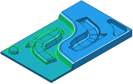
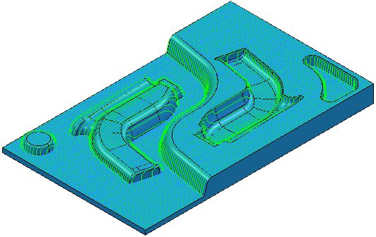
With no boundary selected, the toolpath is calculated over the whole model:
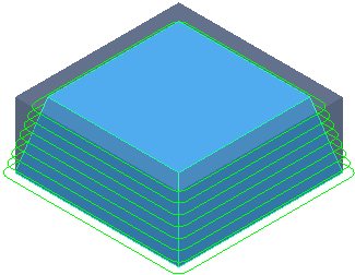
Block Limit — Select an option from the list to specify whether the tool is allowed outside the block or not.
Select
 if the block represents the actual size of the stock you are machining. This maximises the removal of material during area clearance and avoids plunge or ramp entries wherever possible.
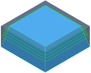
Selecting
 prevents the machining of the lower levels.
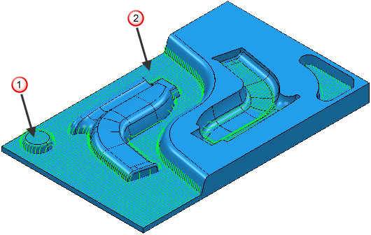
If you start with this model and block:
Selecting
gives:
Selecting
gives:
This option isn't available when Vortex machining as the tool centre must be allowed outside the block. So
is the only allowable option.
- — When selected, enables the tool centre to move outside the block.
- — When selected, the tool centre is limited to the block edge.
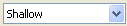
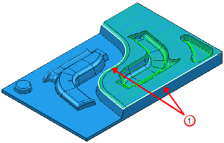
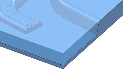
Z Limits — This limits the machining area by Z height. It enables you to machine within a range.
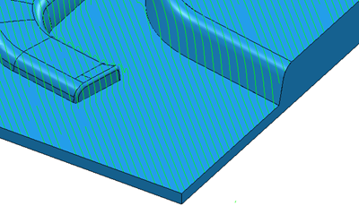
An unlimited toolpath:
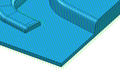
A Z limited toolpath:
In this case, the limits are selected from the model.
Z maximum
 Z minimum
Maximum — Click to select a maximum Z height. Cutting moves are always be below this value.
 Z Height — Use this option to select the Z height graphically.
 — Enter the Z height.
Minimum — Click to select a minimum Z height. Cutting moves will always be above this value.
-
Z Height — Use this option to select the Z height graphically.
- — Enter the Z height.
Exclude Flats — Click to specify that the strategy should not machine flat areas. Use this option if you are using a tool that is not suitable to machine flat areas.
- Flat tolerance — Enter the maximum difference in Z between the highest point and the lowest point on a near-flat surface. The larger the tolerance value, the more the areas that are almost flat are excluded from being machined.