
Holes finds fully defined holes in the surface model as a single surface with a defined top and bottom. This tab is available only for drilling strategies.
The options displayed are the same as those available from the Create Holes dialog, and depend on the Create from option selected:
 — Select the hole feature set where the holes are created.
Hole creation enables you to select how and which hole feature sets are created.
Name root — Enter a name for the hole. Each hole has the root name followed by a number. If there is no root name the hole just has a number.
Create from — Select how to recognise holes.
- Points — Select to create holes from points in the pattern. These points define the centre of the hole.
- Circles — Select to create holes from circles in the model.
- Model — Select to create holes from holes in the model.
- Pairs — Select to create holes from pairs of circles in the model.
- Curves — Select to create holes from any curve in the model that can flatten into a circle in the given workplane.
- Lines — Select to create holes from lines in the pattern. These lines define the top, bottom, and axis of a hole.
- Plunges — Select to create holes from the plunge moves of the active toolpath.
- Normals — Select to create holes from contact-normal moves of the active toolpath.
Create from Model
Tolerance — Enter the tolerance used to create holes.
 — Click to display the
Hole Creation > Options page of the
Options dialog.
— Click to display the
Hole Creation > Options page of the
Options dialog.
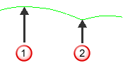
Create compound holes — When selected, creates one compound hole containing several components. When deselected, creates several individual holes (superimposed on each other).
A compound hole is one hole containing several components; in this case, a hole named 1 with components 1 and 2.
If you create them as individual holes, there are two holes named 1 and 2.
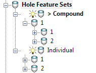
For more information, see Compound Holes.
Use active workplane only — Select to create only the holes that have a Z axis that aligns with the Z axis of the active workplane.
- Find holes in both directions — When Group holes by axis is selected, places holes from both directions into a single multi-axis hole feature set. When Group holes by axis is deselected, splits the holes into two hole feature sets (one for up and one for down).
- Find holes going up — Places the holes going up into a single hole feature set.
- Find holes going down — Places holes going down into a single hole feature set.
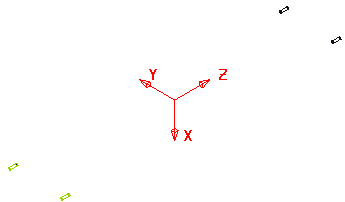
This example uses the RetainerPlate.dgk model. It has an active workplane, and the whole model is selected:
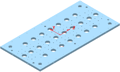
Selecting the Use active workplane only gives:
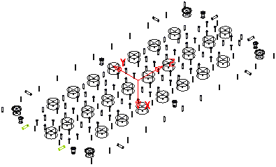
Deselecting Use active workplane only gives:
Group holes by axis — When selected, sorts the holes into hole feature sets by workplane. In this case, your machine tool must have 3+2-axis drilling capability. When deselected, places all the holes in one hole feature set. In this case, your machine tool must have multi-axis drilling capability.
Create holes from partial cylinders — Select to enable PowerMill to create holes from partial cylinders. You may also want to enter a value in the Minimum span angle field to increase or decrease the number of partial holes that PowerMill converts to (complete) holes.
- Minimum span angle — Enter a value to specify which partial holes PowerMill converts to holes. To be converted, partial holes must have an arc angle, or central angle, greater than or equal to the specified angle. Partial holes with an arc angle less than the specified value remain as partial holes. An arc angle, or central angle, is the angle produced by an arc's radii intersecting at the centre of its circle.
Ignore capped cylinders — When selected, creates holes which have at least one open end, and ignores holes with two closed ends.
Edit after creation — When selected, clicking Apply creates the holes and displays the Edit Hole dialog.
Create from anything other than Model
- Absolute — Select to define the top as an absolute Z height.
- Height from Bottom — Select to define the top as a distance from the bottom of the hole.
- Maximum Curve Z
— Select to define the top as the maximum Z height of the selected curve, location
 .
.
- Minimum Curve Z — Select to define the top as the minimum Z height of the selected curve, location
 .
.
 Maximum Z
Minimum Z
Maximum Z
Minimum Z
- Curve centre — Select to define the top as halfway between the top and bottom of the curve (midway between
and
).
- Top of Block — Select to define the top as the height of the top of the block.
- Line Start
— Select to define the top as the start of the line.
Note: This option is available only if you select a Create from of Lines.
 — Enter the height of the top of the hole feature. This is available only if you have a
Create from
of
Points,
Circles,
Curves, or
Lines.
— Enter the height of the top of the hole feature. This is available only if you have a
Create from
of
Points,
Circles,
Curves, or
Lines.
- Absolute — Select to define the bottom as an absolute Z height.
- Depth from Top — Select to define the bottom as a distance from the top of the hole.
- Maximum Curve Z — Select to define the bottom as the maximum Z height of the selected curve, location
.
- Minimum Curve Z — Select to define the bottom as the minimum Z height of the selected curve, location
.
Maximum Z
Minimum Z
- Curve centre
— Select to define the bottom as half way between the top and bottom of the curve. Midway between
and
.
- Bottom of Block — Select to define the bottom as the height of the bottom of the block.
- Line End — Select to define the bottom as the end of the line. This option is available only if you select a Create from of Lines.
- — Enter the height of the bottom of the hole. This is available only if you have a
Create from of
Points,
Circles,
Curves,
Lines, or
Normal.
Upper diameter — Enter the upper diameter of the hole. The Upper diameter is the same as the Lower diameter unless the hole has a Draft angle. This is available only if you have a Create from of Lines, or Normal.
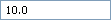
Draft angle — Enter the draft angle of the hole. A value of 0 gives a straight hole with no draft angle.Draft angle of 0:
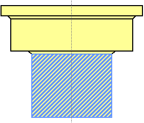
Draft angle of 10:
Group holes by axis — When selected, sorts the holes into hole feature sets by workplane. In this case, your machine tool must have 3+2-axis drilling capability. When deselected, places all the holes in one hole feature set. In this case, your machine tool must have multi-axis drilling capability.
Edit after creation — When selected, clicking Apply creates the holes and then displays the Edit Hole dialog.