
Use the Raster finishing page to create a toolpath by taking a pattern of curves, within a boundary, and projecting points from these curves onto the model.
Fixed direction — Select to specify the angle of passes in the Angle field. When deselected, PowerMill automatically calculates the most appropriate angle.
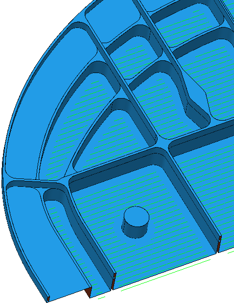
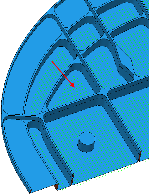
The following example uses the aero.dgk model in the Examples folder.
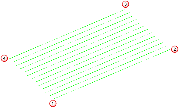
Selecting
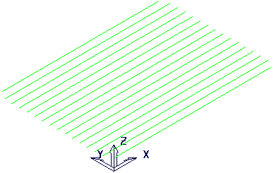
Fixed direction
and entering an
Angle of
0 gives:
Deselecting Fixed direction gives:
Angle —Enter the angle of the passes relative to the X axis.
- Entering an
Angle of
0 gives:
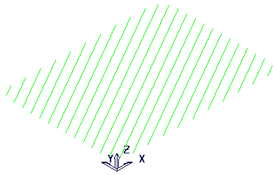
- Entering an
Angle of
30 gives:
Start corner —Select the corner where machining starts. You can choose between four different start corners.
 Lower left
 Lower right
 Upper right
 Upper left
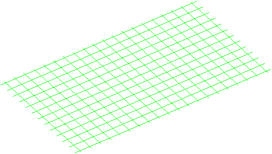
Perpendicular pass
—Select to define a second raster pass perpendicular to the first one.
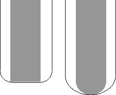
Shallow angle — Enter an angle to specify that the raster pass machines only the areas of the model that are steeper than this angle.
Optimise parallel pass — If a raster toolpath is created with a parallel and perpendicular pass, and with a shallow angle greater than
0, select this option to trim the parallel pass so it does not machine the areas that the perpendicular pass machines.
The examples of the various options in the Perpendicular pass frame are shown in Perpendicular pass examples.
Ordering
Ordering —Select the order in which PowerMill machines the segments.
Arc radius — Enter the radius used to fit arcs between consecutive raster paths. This is the maximum possible arc radius. The maximum value used internally is half the stepover.
Tolerance — Enter a value to determine how accurately the toolpath follows the contours of the model.
Thickness — Enter the amount of material to be left on the part. Click the
Thickness
 button to separate the
Thickness
box in to
Radial thickness
button to separate the
Thickness
box in to
Radial thickness
 Axial thickness
 . Use these to specify separate
Radial and
Axial thickness as independent values. Separate
Radial and
Axial thickness values are useful for orthogonal parts. You can use independent thickness on sloping walled parts, although it is more difficult to predict the results.
. Use these to specify separate
Radial and
Axial thickness as independent values. Separate
Radial and
Axial thickness values are useful for orthogonal parts. You can use independent thickness on sloping walled parts, although it is more difficult to predict the results.
Radial thickness — Enter the radial offset to the tool. When 2.5-axis or 3-axis machining, a positive value leaves material on vertical walls.
Axial thickness — Enter the offset to the tool, in the tool axis direction only. When 2.5-axis or 3-axis machining, a positive value leaves material on horizontal faces.

 Component thickness — Click to display the
Component thickness
dialog, which enables you to specify the thicknesses of the different surfaces.
Component thickness — Click to display the
Component thickness
dialog, which enables you to specify the thicknesses of the different surfaces.
Stepover —Enter the distance between successive machining passes.
 Copy stepover from tool — Click to load the radial depth of cut from the active tool's cutting data. The radial depth of cut is measured normal to the tool axis.
 Edited — When displayed, shows value entered by you (or another user). Click
to change this value to the automatically calculated value.
Edited — When displayed, shows value entered by you (or another user). Click
to change this value to the automatically calculated value.
 Stepover — Enter the distance between successive machining passes.
If you enter a Stepover value, then
changes to
.
 Cusp height — Enter the maximum cusp height and use this value to determine the stepover.
PowerMill calculates the stepover value to give a cusp height of the machining tolerance using the current tool, when machining a plane inclined at 45. This is the worst case cusp height for any given tolerance.
Cusp height — Enter the maximum cusp height and use this value to determine the stepover.
PowerMill calculates the stepover value to give a cusp height of the machining tolerance using the current tool, when machining a plane inclined at 45. This is the worst case cusp height for any given tolerance.
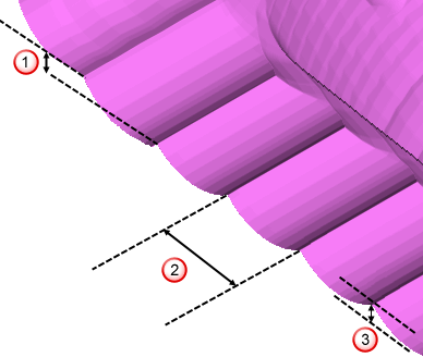 Stepdown
Stepover
Cusp height
Stepdown
Stepover
Cusp height
For more information see Linkage between stepover and cusp height.
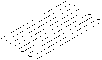
Preview — Click to display the pattern used to create the toolpath.
Draw — Select to display the preview pattern.