
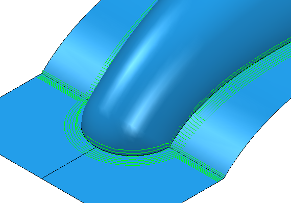
Use the Corner finishing page to create a multiple trace toolpath to clean up corners that occur between non-tangential surfaces.
Output —Select which portions of the toolpath you want to generate.
- Steep — Outputs the portion of the toolpath, which makes an angle of at least the Threshold angle to the horizontal.
- Shallow — Outputs the portion of the toolpath, which makes an angle of up to the Threshold angle to the horizontal.
- Both — Outputs both the steep and shallow portions.
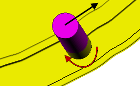
Strategy —Select how to generate the toolpath on the trace lines. This specifies whether the toolpath follows the trace lines or cuts across them.
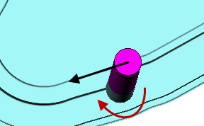
- Along — Select to create a corner toolpath which follows the trace lines. This is best suited to shallow regions.
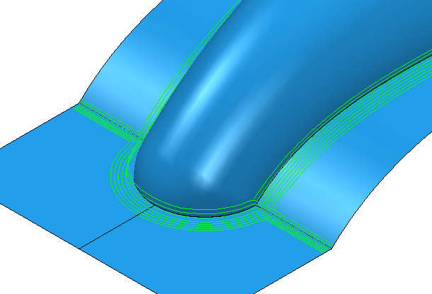
- Stitch — Select to create a corner toolpath which cuts across the trace lines. This is best suited to steep regions.
- Automatic
-
creates a corner toolpath which produces stitches on the
Steep areas and along passes on the
Shallow areas.
Threshold angle — Enter an angle, from the horizontal, at which steep and shallow portions are split when you select an Output type of Steep or Shallow.
Cusp — Enter the cusp height. PowerMill calculates the stepover between tool passes using the cutter geometry and this cusp height.
Uphill cutting — By default, corners of steep regions are machined top-down. Select this check box to reorder the toolpaths so corners are machined bottom-up. Machining bottom-up can minimise tool vibration and therefore produce a better surface finish.
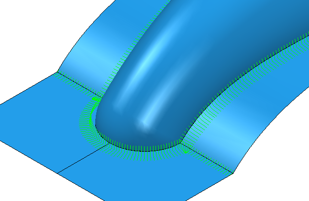
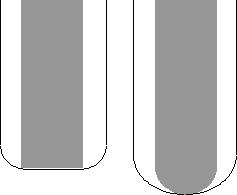
Maximum Passes —Use these settings to determine the number of passes that you want to create. Select Maximum passes and then enter the number of passes you want in the next field.
An Along Corner toolpath without any restrictions to the number of passes.
If you select Maximum Passes and enter the number of passes you want (in this case 2).
Tolerance — Enter a value to determine how accurately the toolpath follows the contours of the model.
Cut direction — Select the milling technology.
Select a Cut Direction from the following:
- Climb — Select to create toolpaths using only climb milling, where possible. The tool is on the left of the machined edge when viewed in the direction of tool travel.
- Conventional — Select to create toolpaths using only conventional or upcut milling, where possible. The tool is on the right of the machined edge when viewed in the direction of tool travel.
- Any — Select to create toolpaths using both conventional and climb milling. This minimises the tool lifts and tool travel.
Thickness — Enter the amount of material to be left on the part. Click the
Thickness
 button to separate the
Thickness
box in to
Radial thickness
button to separate the
Thickness
box in to
Radial thickness
 Axial thickness
 . Use these to specify separate
Radial and
Axial thickness as independent values. Separate
Radial and
Axial thickness values are useful for orthogonal parts. You can use independent thickness on sloping walled parts, although it is more difficult to predict the results.
. Use these to specify separate
Radial and
Axial thickness as independent values. Separate
Radial and
Axial thickness values are useful for orthogonal parts. You can use independent thickness on sloping walled parts, although it is more difficult to predict the results.
Radial thickness — Enter the radial offset to the tool. When 2.5-axis or 3-axis machining, a positive value leaves material on vertical walls.
Axial thickness — Enter the offset to the tool, in the tool axis direction only. When 2.5-axis or 3-axis machining, a positive value leaves material on horizontal faces.

 Component thickness — Click to display the
Component thickness
dialog, which enables you to specify the thicknesses of the different surfaces.
Component thickness — Click to display the
Component thickness
dialog, which enables you to specify the thicknesses of the different surfaces.