
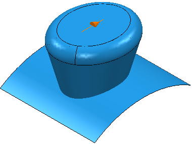
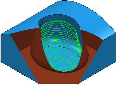
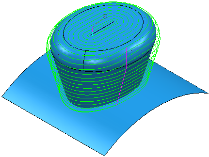
Use the Parametric spiral finishing page to create a spiral toolpath which starts spiralling from a specified pattern and which terminates at the specified surfaces.
Central curve specifies a curve or point which determines the start of the toolpath when machining a boss, or the end of the toolpath when machining a pocket. The curve must be a pattern containing one segment. You can use a closed or open pattern.
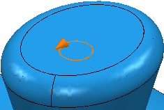
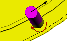
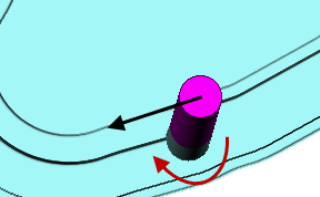
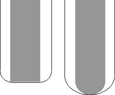
When you select a central curve, it is instrumented so you can see the orientation of the spiral curve.
An instrumented open curve:
An instrumented closed curve:
 Create pattern — Click to create a new empty pattern.
 Selected pattern — Select a pattern from the list. If no pattern is displayed, or
 is selected, then no pattern is selected. The list contains a list of all available patterns.
 Curve Editor— Click to display the
Curve Editor
for the selected pattern. If no pattern is selected,
PowerMill creates a new pattern.
Curve Editor— Click to display the
Curve Editor
for the selected pattern. If no pattern is selected,
PowerMill creates a new pattern.
 Select picked pattern — Click to select a pattern by picking in the graphics window, rather than by name in the
Select pattern list.
Select picked pattern — Click to select a pattern by picking in the graphics window, rather than by name in the
Select pattern list.
 Collect curves — Click to copy the selected curves into the pattern. This provides a fast, powerful means of extracting curve geometry from a surface model and copying it into the active pattern/boundary. For more information, see the
collecting curves example.
Collect curves — Click to copy the selected curves into the pattern. This provides a fast, powerful means of extracting curve geometry from a surface model and copying it into the active pattern/boundary. For more information, see the
collecting curves example.
Outer limit — None:
Outer limit
— The set containing surface
 :
:

If there is no base surface and an Outer limit of none:
Undercut — Enter an angle to specify the undercut relative to the Central curve. You can have a different angle on each side of the curve. The curve direction is displayed when you select a Central curve. If the slope of the part (measured from the vertical) is less than the Undercut angles you can machine the part.
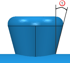
The Undercut angle is measured from the vertical.
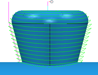
If the angle is the same as, or larger than
 the complete profile is machined:
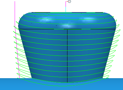
If the angle is the less than
the complete profile is not machined:

If you have a different Left angle to Right angle then the toolpath follows the profile differently on either side of the Central curve.
This option is more useful when you are machining an asymmetric part.
- Angle — Enter the maximum allowable undercut angle. This option is available when you select a point or a closed curve as your Central curve.
- Left angle — Enter the maximum allowable undercut angle to the left of the Central curve. This option is available when you select an open curve as your Central curve.
- Right angle — Enter the maximum allowable undercut angle to the right of the Central curve. This option is available when you select an open curve as your Central curve.
Tolerance — Enter a value to determine how accurately the toolpath follows the contours of the model.
Direction — Select the milling strategy:
- Towards centre — The toolpath is generated from the surface to the curve.
- From centre — The toolpath is generated from the curve to the surface.
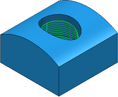
- Clockwise — Select to produce a conventional milling toolpath when machining a pocket and a climb milling toolpath when machining a boss.
- Anticlockwise — Select to produce a climb milling toolpath when machining a pocket and a conventional milling toolpath when machining a boss.
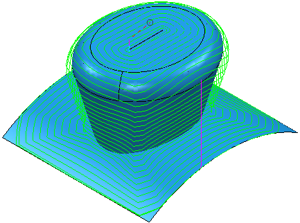
Conventional milling toolpath:
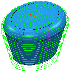
Climb milling toolpath:
 Note: A (near) vertical Outer Limit is likely to produce a better pocket toolpath than a (near) horizontal limit.
Thickness — Enter the amount of material to be left on the part. Click the
Thickness
 button to separate the
Thickness
box in to
Radial thickness
button to separate the
Thickness
box in to
Radial thickness
 Axial thickness
 . Use these to specify separate
Radial and
Axial thickness as independent values. Separate
Radial and
Axial thickness values are useful for orthogonal parts. You can use independent thickness on sloping walled parts, although it is more difficult to predict the results.
. Use these to specify separate
Radial and
Axial thickness as independent values. Separate
Radial and
Axial thickness values are useful for orthogonal parts. You can use independent thickness on sloping walled parts, although it is more difficult to predict the results.
Radial thickness — Enter the radial offset to the tool. When 2.5-axis or 3-axis machining, a positive value leaves material on vertical walls.
Axial thickness — Enter the offset to the tool, in the tool axis direction only. When 2.5-axis or 3-axis machining, a positive value leaves material on horizontal faces.

 Component thickness — Click to display the
Component thickness
dialog, which enables you to specify the thicknesses of the different surfaces.
Component thickness — Click to display the
Component thickness
dialog, which enables you to specify the thicknesses of the different surfaces.
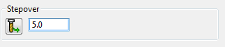
Maximum stepover — Enter the maximum distance between successive machining passes.
 Copy stepover from tool — Click to load the radial depth of cut from the active tool's cutting data. The radial depth of cut is measured normal to the tool axis.
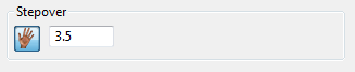
 Edited — When displayed, shows value entered by you (or another user). Click
to change this value to the automatically calculated value. Click
to change this to the automatically calculated value.
Edited — When displayed, shows value entered by you (or another user). Click
to change this value to the automatically calculated value. Click
to change this to the automatically calculated value.
- Stepover — Enter the distance between successive machining passes.
Note: If you enter a Stepover value then changes to
.