
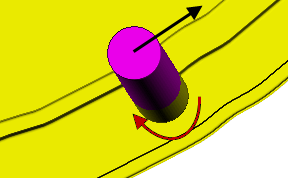
Use the Wireframe swarf finishing page to create a swarf toolpath from two wireframe curves. PowerMill creates a toolpath cutting with the side of the tool as the tool follows the two curves. As with Swarf machining you must be able to create a developable surface from the two wireframe curves. For more information see Swarf machining.
Drive curve — Use these settings to determine which surface, or set of surfaces, are used to create the cutting moves.
- Top pattern — Select the top wireframe curve.
- Bottom pattern — Select the bottom wireframe curve.
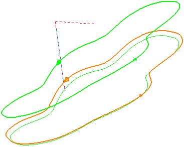
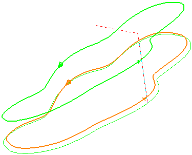
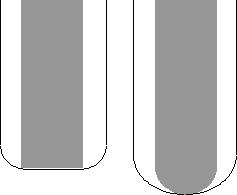
- Wireframe side — Select which side of the pattern you want to machine.

 - left side
 - right side
Wireframe side - Left:
Wireframe side - Right:
- Angular rulings tolerance — Enter the angular tolerance used when generating ruling between two wireframe curves. This creates the ruling by matching the top and bottom normals within the angular tolerance. This is similar to the creation of developable surface from two rail curves.
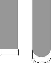
- Radial offset — Enter the gap between the tool and the surface.
 —
Radial offset:
0
— Radial offset:
5
—
Radial offset:
0
— Radial offset:
5
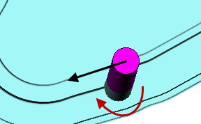
- Minimum fanning
— As the toolpath moves from one surface to another there can be a change in the ruling direction. Because the tool aligns itself with the ruling direction, you have to specify the distance over which the tool can change from one ruling direction to the next. The fanning distance is measured as the smallest movement on either surface edge (or the distance the closest part of the tool is to the opposite part of the surface before fanning starts).
PowerMill automatically increases the
Minimum fanning distance if the value specified causes gouging.
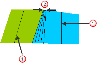 — Ruling direction.
— Fanning distance.
— Ruling direction.
— Fanning distance.
- Fan at end on planes — Select so fanning occurs only in the end region of a plane. When deselected, fanning occurs everywhere.
 Select picked pattern — Click to select a pattern by picking in the graphics window, rather than by name in the
Select pattern list.
Select picked pattern — Click to select a pattern by picking in the graphics window, rather than by name in the
Select pattern list.
Select picked pattern — Click to select a pattern by picking in the graphics window, rather than by name in the
Select pattern list.
Gouge check — Select this option so PowerMill checks the toolpath to see if any part of it gouges or deselect to turn gouge checking off.
Degouge tolerance — Enter the maximum distance, normal to the surface, that the toolpath can move to find a safe position. If gouges greater than this value are detected, then the tool is lifted axially to avoid the gouge.
Tolerance — Enter a value to determine how accurately the toolpath follows the contours of the model.
Cut direction — Select the milling technology.
Select a Cut Direction from the following:
- Climb — Select to create toolpaths using only climb milling, where possible. The tool is on the left of the machined edge when viewed in the direction of tool travel.
- Conventional — Select to create toolpaths using only conventional or upcut milling, where possible. The tool is on the right of the machined edge when viewed in the direction of tool travel.
- Any — Select to create toolpaths using both conventional and climb milling. This minimises the tool lifts and tool travel.
Thickness — Enter the amount of material to be left on the part. Click the
Thickness
 button to separate the
Thickness
box in to
Radial thickness
button to separate the
Thickness
box in to
Radial thickness
 Axial thickness
 . Use these to specify separate
Radial and
Axial thickness as independent values. Separate
Radial and
Axial thickness values are useful for orthogonal parts. You can use independent thickness on sloping walled parts, although it is more difficult to predict the results.
. Use these to specify separate
Radial and
Axial thickness as independent values. Separate
Radial and
Axial thickness values are useful for orthogonal parts. You can use independent thickness on sloping walled parts, although it is more difficult to predict the results.
Radial thickness — Enter the radial offset to the tool. When 2.5-axis or 3-axis machining, a positive value leaves material on vertical walls.
Axial thickness — Enter the offset to the tool, in the tool axis direction only. When 2.5-axis or 3-axis machining, a positive value leaves material on horizontal faces.
 Component thickness — Click to display the
Component thickness
dialog, which enables you to specify the thicknesses of the different surfaces.
Component thickness — Click to display the
Component thickness
dialog, which enables you to specify the thicknesses of the different surfaces.
Preview — Click to produce a quick preview toolpath over the projection shape.
Draw — Select to display the preview pattern.