
Use the Radial finishing page to create a 2D radial pattern within a boundary and then projects it onto the model. This pattern is then machined.
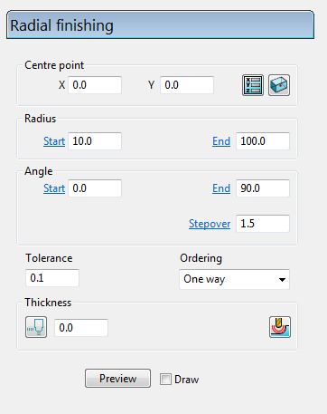
- Centre point — Use these settings to define the origin of the radial pattern. Because the pattern is centred at the origin of the active workplane, it may need moving before it is projected onto the work surface.
 — Click to display the Position dialog. Use the dialog to manually enter coordinates and locate items in the graphics window.
 Reset to block centre — Click to automatically centre the radial pattern on the middle of the block.
- Radius Start / Radius End — Enter values to control the dimensions of the pattern and the direction of the first pass.
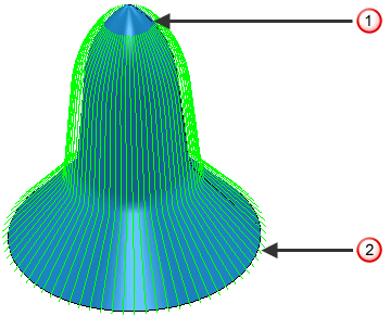
This toolpath has a Start Radius of 10 and an End Radius of 100.
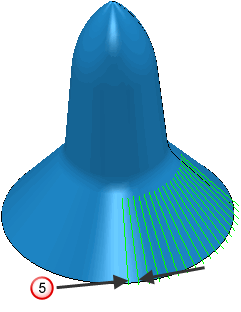
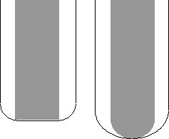
This toolpath has a Start Radius of 27 and an End Radius of 100.
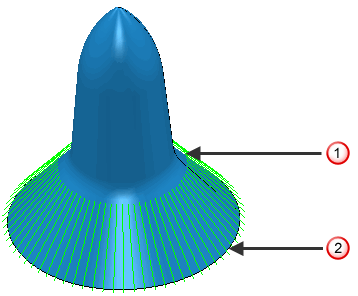
 — Start radius
 — End radius
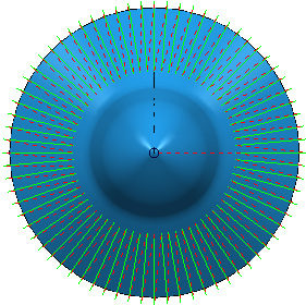
 - Angle Start / Angle End / Stepover —Enter values to determine over what portion of a full circle the picture is generated, and whether the tool travels in a clockwise or counter-clockwise direction.
This toolpath has a Start Angle of 0
 and an End Angle of 360.
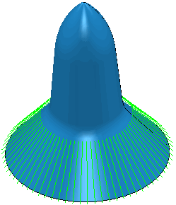
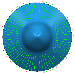
This toolpath has a Start Angle of 0
and an End Angle of 90.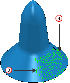
 — Start angle
 — End angle
Angles are measured counter-clockwise from the positive X axis when using Z-oriented tools and from the positive Z axis when using X-oriented tools.
When the start angle is greater than the end angle the tool travels clockwise.
When the start angle is less than the end angle the tool travels counter-clockwise.
If you want to machine an area counter-clockwise starting at 350
and ending at 10 you need to think about the values you enter. If you enter a Start Angle of 350 and an End Angle of 10 then PowerMill will travel clockwise and machine the opposite of what you want. So you must enter a Start Angle of 350 and an End Angle of 370 to get the desired result. - Stepover — Enter the distance between successive machining passes. This is the maximum distance between passes.
 — Stepover
 - Ordering —Select the order in which PowerMill machines the segments.
- One way
- Two way joined
- One way
Tolerance — Enter a value to determine how accurately the toolpath follows the contours of the model.
Thickness — Enter the amount of material to be left on the part. Click the
Thickness
 button to separate the
Thickness
box in to
Radial thickness
button to separate the
Thickness
box in to
Radial thickness
 Axial thickness
 . Use these to specify separate
Radial and
Axial thickness as independent values. Separate
Radial and
Axial thickness values are useful for orthogonal parts. You can use independent thickness on sloping walled parts, although it is more difficult to predict the results.
. Use these to specify separate
Radial and
Axial thickness as independent values. Separate
Radial and
Axial thickness values are useful for orthogonal parts. You can use independent thickness on sloping walled parts, although it is more difficult to predict the results.
Radial thickness — Enter the radial offset to the tool. When 2.5-axis or 3-axis machining, a positive value leaves material on vertical walls.
Axial thickness — Enter the offset to the tool, in the tool axis direction only. When 2.5-axis or 3-axis machining, a positive value leaves material on horizontal faces.

 Component thickness — Click to display the
Component thickness
dialog, which enables you to specify the thicknesses of the different surfaces.
Component thickness — Click to display the
Component thickness
dialog, which enables you to specify the thicknesses of the different surfaces.