
Project Using Normal Vectors
Normal vectors are a way to tell the laser projector(s) not only where to project the laser, but also the outward direction of each point. This can be useful information on highly curved or complex parts. For example, if the part is a cylinder, then the normal vectors might all radiate out from the center axis of the cylinder. A laser projector could only project the points that were on the near side of the tube, and would not try to project any points that had normal vectors facing away from its current location.
There are multiple ways to obtain and edit normal vectors associated to laser geometry.
Normal Vector Settings
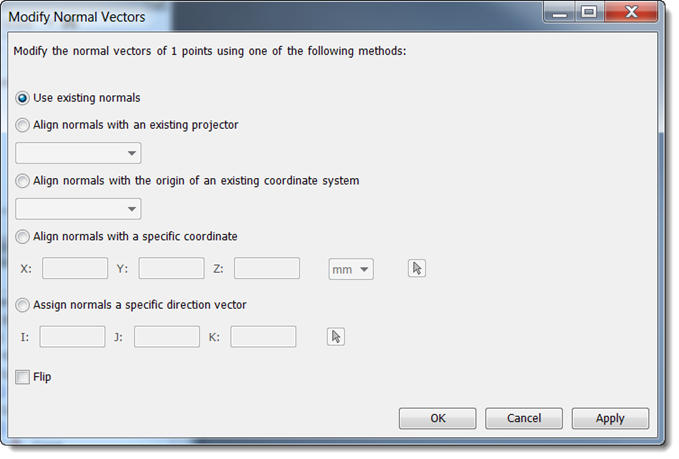
| Use existing normals | Leaves the normal vectors as they are on each selected point. It is useful in conjunction with the flip checkbox. |
| Align normals with an existing projector | Points the normal vectors for all selected geometry towards the selected laser projector. In order to select a projector from the list there must be at least one projector defined in your laser data tree. |
| Align normals with the origin of an existing coordinate system | Points the normal vectors for all selected geometry towards the selected axis system. In order to select an axis system from the list, it must have been previously defined. |
| Align normals with a specific coordinate | Points the normal vectors for all selected geometry towards the exact location entered in the X, Y, and Z boxes. The default units are millimeters, but can be changed to other common units in the drop-down list. |
| Assign normals a specific direction vector | Points the normal vectors for all the selected geometry towards the unit vector described by the I, J, and K values. This option will not point all of the normal vectors towards one specific point in space like the other options above. Rather, it creates a normal vector for each point individually by creating an offset from the original point location. |
| Flip | Point normal vectors outward towards the outside of the tool. |